Cedar Porch Side Table

When we first moved in to our house we bought some fancy wicker chairs for the back porch. They are lovely, but we weren’t wild about their side table options. “I’ll just build something!” I said. 3 years later we were still using a junky wooden folding table the previous owners had left. To be fair, it was at the right height, but was rather small.

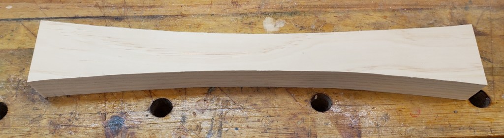
I kept having this idea of using cedar 2x4s to make the legs, and cutting a bow in the legs to make them match the chairs. I used some junky pine to cut two rough legs and mock up an inward and outward bow. The inward concave version kind of matches how the chairs are shaped and is how I will proceed.

I picked cedar because it is available to my local hardware store, is reasonably priced and is supposed to be good for outdoor applications. I did not realize how soft it is and probably won’t build anything else nice with it again. It dents and tears out really easily.


Table Top

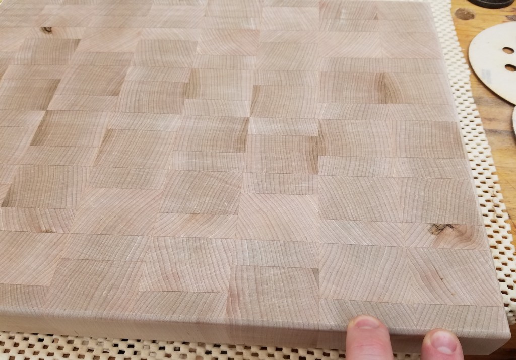
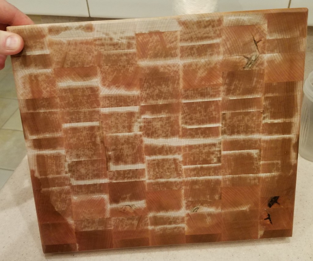
I knew the size I wanted the table top to be so I started there and will build the legs and aprons to follow. I mixed some darker and lighter wood to create a little contrast on the top. These were the straightest cleanest grained pieces I could find. They had a bit of a split that looked ok to start with, but got more apparent as I milled.

I hadn’t used my hand tools in a while but used this chance to flatten all the boards and check grain orientation. After glue up I picked up the top and figured out how bad those splits were. The whole top would flex around those splits like a taco. These will have to get fixed.

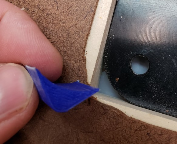
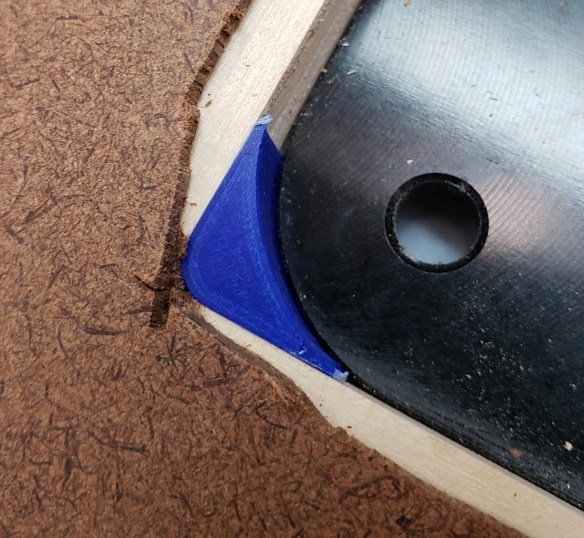
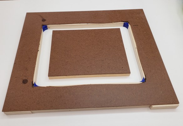
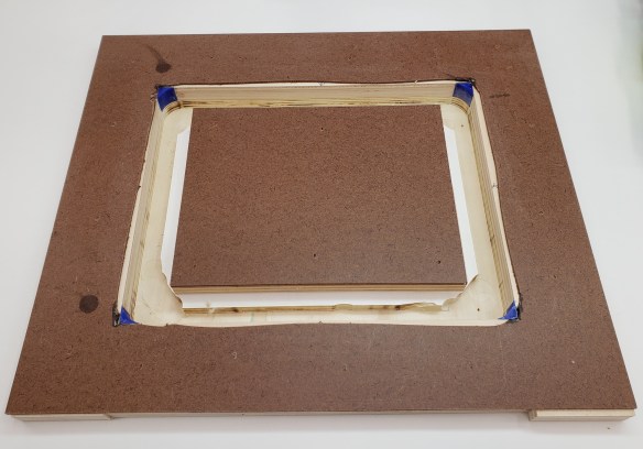
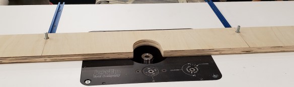
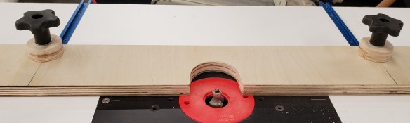
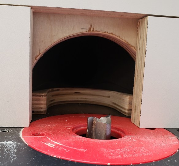
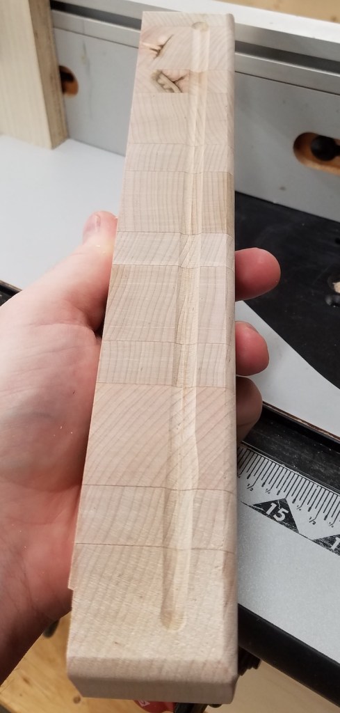
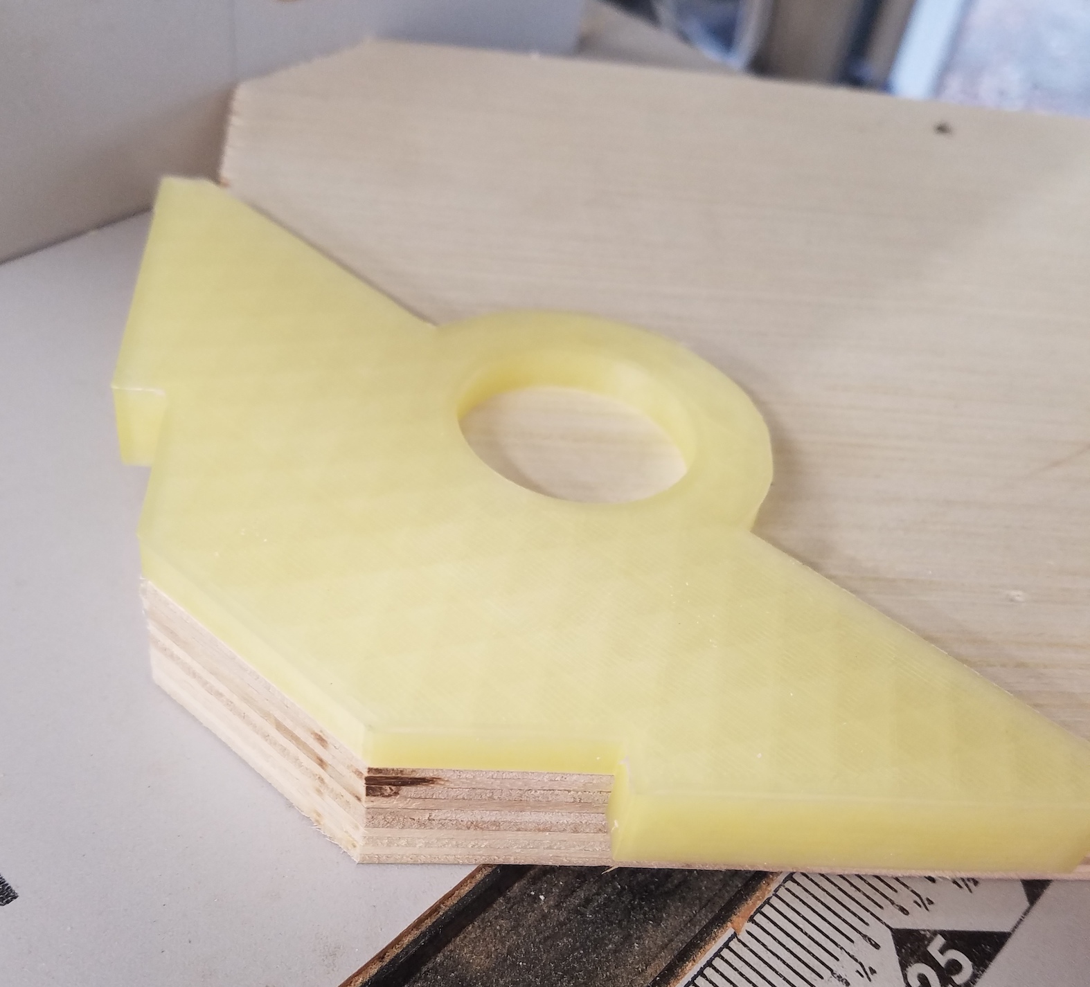
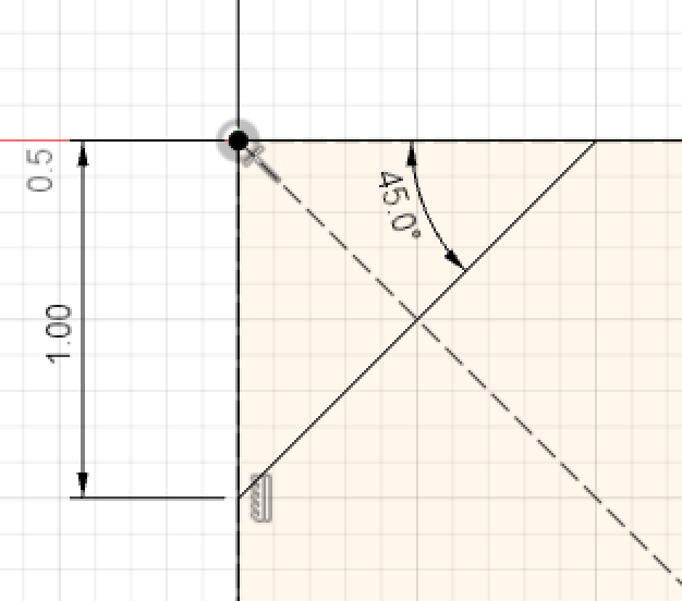
My quick little side table is becoming less quick. I have never done butterfly keys, but why not start now?! It took a few iterations but I made a key shape that my pattern bit would replicate and matched the corner radius a 1/4″ router bit would produce.

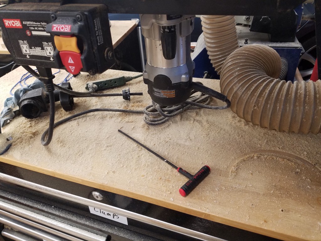
First you use double sticky tape to place the template. Plunge route the socket that will accept a key. Tape a template to the top of a key blank and pattern route the key. I made them tall enough to resaw and get two keys per pattern. I cleaned up the socket area, glued in the key and then planed the area flush.

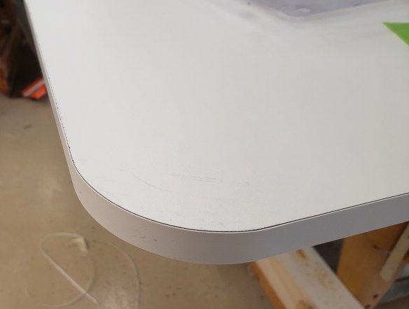
The other side of the top looks much cleaner and was originally what I was going to show. After the keys turned out so well I showed it to my wife and she thought it looked better that way. Not sure if it qualifies as Wabi-Sabi or not, but it feels like it to me. With all the keys installed the table top feels really solid and doesn’t flex anymore. I trimmed up the edges and put a roundover and chamfer all the way around.


Legs

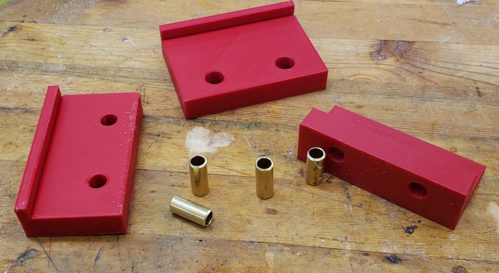
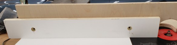
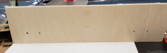
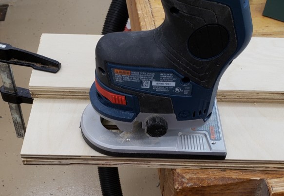
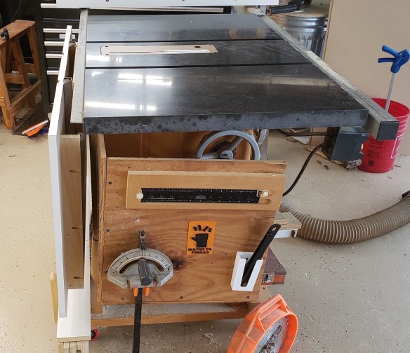
Moving on to the legs I repeated the steps used to create the initial 2×4 concept pieces only I used a pattern to speed things up. I started by roughing out each leg on the bandsaw getting as close to the line as I dared without going over. Price Is Right rules apply here.

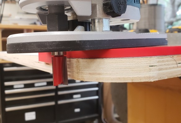
With the legs roughed I again used the pattern bit to clean them up to the line. I just bought this fancy compression pattern bit because of how much I do pattern routing. Oops, the piece is too tall to cut it all in one go. Off goes the top bearing, I will have to take one bite, then increase the bit height to do it again.

I got all the routing done, but was still left with a pretty rough surface. Cedar is so soft it tears more than it cuts with the router. I actually got to break out my spokeshave in order to clean up the leg faces. Probably overkill considering I am going to round over all the legs, but it was still fun and good practice.


Aprons and Assembly

I am leaving the legs square until the last minute, they bruise like crazy and I want to preserve their shapes. Instead of trying to cut mortise and tenons I just used pocket hole screws. I would probably blow out a side wall trying to mortise these legs, and the pocket hole screws are outdoor rated.

To get the shape right I cut the aprons a bit long and assembled with clamps to get a feel for the size of the base. Then, I was able to cut the width and length down until the proportions looked good. Not as fancy as drawing it all out ahead of time and knowing the exact dimensions, but better than just making up round numbers and building it regardless of looks. I am no master designer, but I am getting better. Once I got the dimensions right I drilled the pocket holes and did a final test assembly.

With the dimensions all set I could do my roundover on the legs and perform final sanding on everything. Once again the cedar bit me. The roundover, which I did in multiple gentle bites totally chipped out the bottoms of the legs. I could trim them down a smidge, but I figure the rabbits will chew down there anyways, so whatever.

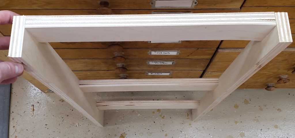
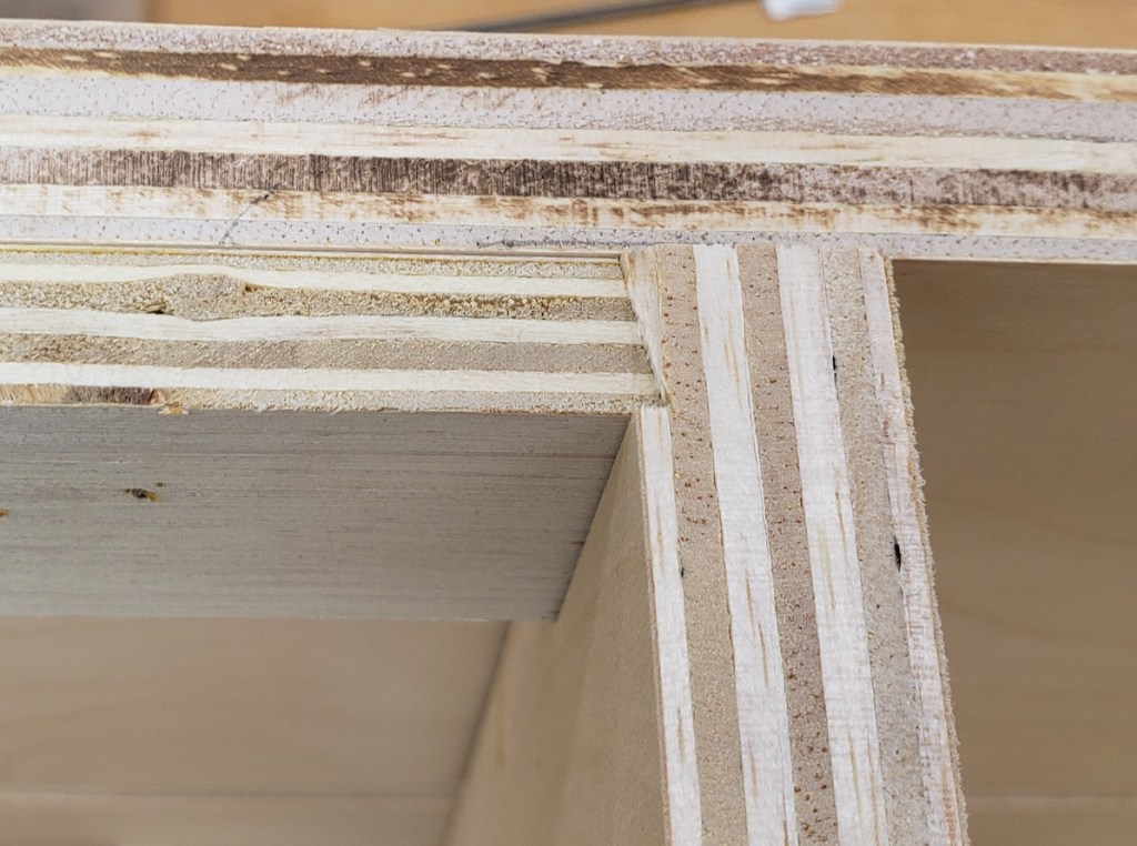
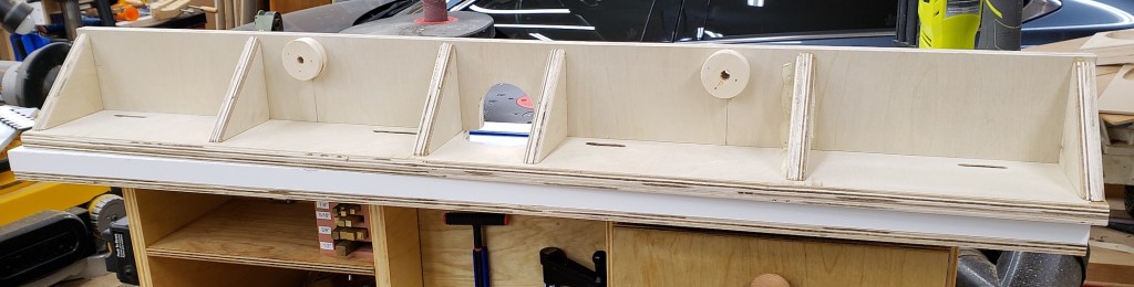
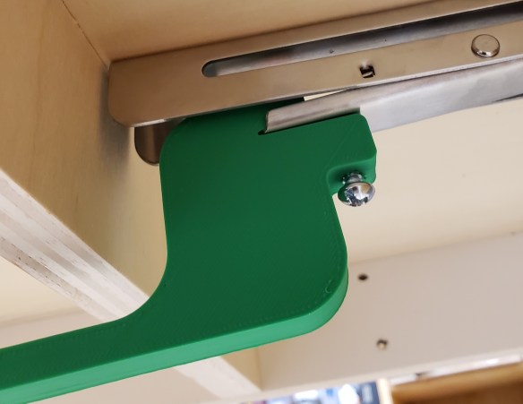
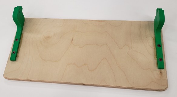
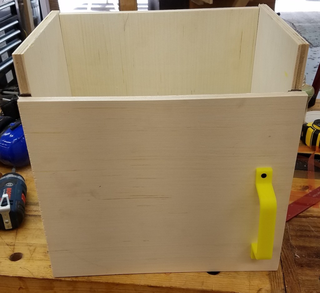
I finished all the parts individually with a spar polyurethane that I thinned down to make a wiping poly. It is dark to help keep UV damage down and it did make the wood take on a lovely color. To attach the top to the base I made a cleat with slotted holes so the table could move and not pull apart. I also added a hidden back shelf so we could sit things behind the table. Our son likes to pull out the tissue box and assault the fan remote. These can be stored in the back.

I attached some plastic slider feet to keep it from having direct contact with the ground. The table never sees direct sun or rain, and between the wood choice and finish it ought to last forever. The softness of the wood means that a child and two rabbits will destroy it mechanically before nature ever does. Done just in time for porch season to set in.

Folding Helping Tower

A helping tower is like a step stool you use in the kitchen with a child. It gets them up to a height to be able to help out with basic cooking tasks. Unlike a basic step stool, this has sides and a back so they can be kept in place, and not easily fall off. There are a million different examples online, but most all of them are bulky (by necessity) and end up being a bit of an albatross in the kitchen. I wanted a folding one that could be packed away easily. It took a lot of prototyping, but I did it.

I normally jump into projects, but this one was a very slow methodical trial and error build over nearly 2 months. A broken AC and baby tasks stretched that out a bit. The front frame of the device consists of two permanent uprights with an upper and lower stretcher. To those uprights, a set of folding sides are attached. The right upright is thinner so that the two fold over each other in an overlapping pattern.

The middle stretcher will hold the step and let it swing into place. I needed a strong stop that would support the step and draw the sides into the step. I used a dovetail bit on the bottom of the step to make a slightly angled groove. The stops had the same angle in reverse. Now, the more weight put on the step, the tighter it will draw the sides in.

The seat can fold up and the sides fold in. Everything is compact and easy to deploy. The stops are only 1/2″ thick and don’t interfere with the fold up.

It needed some kind of back to keep people from falling off backwards. A simple swing arm accomplished this task. It was narrow enough so as not to interfere with the unit’s ability to pack up. This had all the rough mechanics I wanted, but was narrower and not as deep as I felt it should be. Also I wanted the step portion to be adjustable as the child grows. On to the next prototypes.


I am going to use dowel nuts and binding screws to make something that was strong, but could be removed and reassembled. It would take a number of holes drilled in the right places to make that work. I planned the sizes of the parts and printed out drill guides that would hold brass tubes to act as drill bushings. The brass won’t last forever, but is easy to cut and insert, and helps keep the hand drilling accurate.

First up I clamped the jig in place and used a transfer punch to mark the centers of where the barrel nuts will go. This makes drilling on the drill press easy.

Next to accommodate the bolts, I need to drill a long hole end-on to meetup with the cross holes. This can’t vary much and the parts are too long to use the drill press, thus the drill jig idea.

With both sets of holes accurately drilled, the nuts and bolts will meet up in the correct spots.


With the folding and adjusting mechanics worked out I could move on to the real thing. I selected 1×3 pine for the uprights and spreaders. The step spreader got its holes drilled with the above jigs, and the other two spreaders received a set of fair curves thanks to my new drawing bows.

Part of the assembly folding out and being stable is having the sides only fold out 90 degrees. They must positively stop when they reach the right angle. I do this by firmly clamping the sides and uprights together and routing a small pocket for the hinges. This 3d print has a center-line mark on it and is perfectly spaced to make a tight mortise for the hinges. The result is a flush hinge and sides that do not swing out past where you need them.

I assembled the step and determined how high it could go when folded up. Too high and the step hits the top spreader. Marking those places I could make a row of holes that would allow the step assembly to adjust as needed. The sides and uprights got a set of holes placed every 2 inches.

To lighten the structure and add something fun, I printed a series of shape templates. Double sticky tape holds them down, and a plunge router cuts them out quickly. I made 8 unique shapes and it really adds a lot.

I put the center spreader in at the top most position and marked where the stops should be. Each one has two t-nuts hammered in place. Bolts go in from the outside to hold those securely. Now to adjust the height you have 8 bolts to remove. 4 from the stops, and 4 from the folding step. The final unit is light, compact when folded, looks decent (even though most of it is plywood), and should have enough room for any kid small enough to need it. The swinging back stop is made with another set of dowel nuts and binding screws. Everything got a coat of shellac as basic protection.

As a final bonus, I was able to cut the shapes out carefully enough that they all survived in tact. I rounded the edges and shellacked them as well.

I want to be able to re-create this again in the future. Here is a rough parts list with sizes. Dowel nuts and binding screws are both 1/4-20s.

QtyDescription
6Dowel Nut
4Binding Screw, 5/8”
6Binding Screw 1-3/16”
4T Nut
8Pan head screw, 1-1/2”


1Back Bar: 18-1/4 x 1-1/2”
3Spreaders: 16 x 2-1/2”
1Upright Left: 38 x 2-1/2”
1Upright Right: 38 x 1-3/4”
1Side Left: 36 x 10”
1Side Right: 36 x 10-3/4”
1Step: 16 x 11-1/2”

Router Table Top and Fence

I have been using my new router setup for a number of weeks now. The lift is fantastic, the top is a little wonky and too soft, and the fence is barely adequate. I am settled enough on some of my other projects and have spent some time thinking out how I want to build a final top and fence. So, let’s get building and address all the issues my first top created.

The first thing to fix is the cutout the router lift fits into. The radius required is a size of router bit I don’t have. My last attempt didn’t go well. This time, I have a good plan. First, I put the router lift down on a piece of hardboard and snugged up pieces of plywood next to it. I then glued and weighted the plywood to the hardboard so it would provide a very tight hold of the lift top plate.

That all made the edges fit snugly, so I know there won’t be any wiggle when I drop the router lift in. Next, to solve the radius problem I just 3D printed some corners that take up the extra space. Now, the router bit I have will follow the contour and there won’t be any gaps at the corners. I used thin CA glue to hold the printed corners in place.

With the cutout template finished I double sticky taped it down to a big piece of laminate faced plywood and got routing. The first pass hogged out the lip that the router lift will sit on. A jigsaw opened up the rest.

I checked the fit and it is wonderful. There is almost no slop, and the corners match the lift well.

I cut a piece of 3/4″ plywood to go under the laminate top to act as support. I sat the two pieces on my flat table saw top and went around with a straight edge and flashlight to check everything. I found some slight bows and used cawls to clamp everything flat, then slowly brad nailed everything together.

With everything tacked together I moved the top to the router base I built earlier. I found some slight dipping in the center, so I cut brass shims to bring the top back to flat when everything was screwed down. With the top in place, flat, and securely fastened, I added edge banding all the way around to help protect the laminate from getting chipped.


Next I wanted to add a number of t-tracks to the top for featherboads and to keep the fence in place. My router produces a ton of dust when doing a big cut and my fixed base porter cable 890 series doesn’t come with any collection port. A few iterations of printing got me this two piece design that I glued together. It goes in where the edge guide would normally plug in.

The start of the cut usually generates a lot of dust, but once the grooves got going the shroud did a good job picking up most of the dust. There probably aren’t any 100% solutions, but this does save a lot of mess. The grooves turned out well!


The top is nearly complete. I just need to do the final installation of the lift. First, I wanted to reinforce the places where the leveling set screws will land. The plywood is too soft, and I expect they will sink in with time. On my last top I used CA glue to shore up the area. This time I found some 1/16″ brass to line those areas. Once bonded, the leveling went quickly. All the effort I spent getting the table top level means the router lift plate can be perfectly flush all the way around. No catches or dips at the transitions.


The Fence

With the table top finished, I was ready to move on to the fence. Having it clamp at the edges worked in my last fence adaptation, but the center tended to flex. That is the most important place to keep still, so I added the t-track in closer to the center to keep the fence stable near the bit. I cut out some 3/4″ plywood to act as a base an front face for the fence.

I put in knobs to clamp the fence down, and added spacers to move the height of the knob up. The fence is tall enough it needs a little boost to make it easier to reach.

I cut out laminate plywood sections to make movable fence faces. I set them against the front of the fence and marked the spots where a slot would need to start and top. I should have drilled out the ends of the slot and routed the middle. The full depth cut got a little squirley in places. Oh well, the fence faces open and close easily.

Now that I know where my hands will be going to tighten the fence and faces, I know where there is free space to add ribs. These triangular ribs will stabilize the fence front and keep it stiff. I just glued and nailed them in place.

To finish off the fence I cut a strip of laminate to go across the top of the moveable faces. It makes the total height 5 inches and holds a t-track that goes the whole length of the fence.

The fence is done, but it still doesn’t have any dust collection. I printed a duct section to screw down just behind where the router bit will be. This combined with the dust collection built into the cabinet means that very little dust will escape this unit.

That puts the final touches on the fence. While I was at it, I cut a hand full of extra moveable faces and screwed them to the back of the table cabinet as spares. I also cut a full length extra tall fence that moves the total height up to 6 inches.

These upgrades should make the whole router setup really clean and fast to operate. Combined with the base I built earlier I am all set on the router front and am ready to tackle a lot of new future projects!

Table Saw Outfeed Extension

I already had an outfeed extension for my table saw. I only built it two years ago. Why make a new one? Well I love it and use it all the time, but often wish it was bigger. Wide sheet goods don’t get enough support on the side, and longer things still fall off the back of it. I have more space in my new house, and I saw a great idea from Wood Work Web. Colin over at that site used these clever folding brackets to hold the extension and in a followup added a really easy release bar. First, let’s say goodbye to the old extension.

How did I manage to get nice laminate faced plywood in these times? As it turns out if you order enough sheets of plywood from the cabinet store, they will deliver it all for a pretty reasonable fee. I got enough supplies to last me for months, supported a local business, and did it in a socially distanced manor!

The folding brackets are a cheap amazon versions of what was used in the video. They feel sturdy enough, but aren’t actually square. A deeper read of the comments would have highlighted that fact. They slope the table away from the saw. That is ok by me, but in a lot of other applications, that could be a deal breaker. After removing the old top, I was able to re-use the bolted on pine board that served as the anchor point for my previous extension. I spaced the extension far enough away to clear my fence and its hardware. There is a bolt head (circled in red) that sits well below the height of the table. I have to avoid it or risk limiting the fence’s movement. Once installed the extension folds very compactly.


Rounded Corners

I really wanted to cut some corners on this build. I know I will be lazy and leave the extension up most of the time, and I work a lot around the table saw at my router and back into the saw and extension often. Rounding these edges would make them less painful. I started with a 2.5″ radius template and used it to mark and jig saw the corner off. Next I stuck it down with double sticky tape and used a template tracing bit to smooth out the remainder.

Once both corners were done I applied a white edge banding to all the edges. This should help protect the laminate top from getting chipped or damaged. I trimmed all the excess with a sharp knife.

Miter Slots

My last extension didn’t have any miter slots. If I used any kind of sled or miter gauge they would bonk against the table. I took the time to install them in this top. I clamped plywood to the top just outside of where the miter bar would pass. I then used a short tracing bit route down enough to allow clearance for the bar. I then picked up the plywood, lined it up with the other side of the bar and routed again. It wasn’t as exact as a purpose built slot template, but was quick and worked well. With the two slots routed, I soaked the edges in thin CA glue to help reinforce them and prevent the top from chipping off.

Things were starting to look really nice and functional. I did notice that my last top had a slight warp to it. I may have stored too many things on it. To prevent warpage in this top, I took it off and screwed on a set of supports underneath. These should help keep it flat.

Release Bar

This was kind of above and beyond, but why not go all out? I wanted to add a release bar like Colin did. Between the supports I added, and the way it was anchored to the saw, there wasn’t room to do what he did. Instead I 3D printed a little funky zigzag bracket. It is threaded to accept a #10 screw. I drilled a hole in the bracket release tab so the screw would go into that hole and prevent the bracket from sliding off.

That printed part gave me a long arm to attach a wide piece of plywood. This would be the thing I press up against to release and lower the extension. I clamped it in place to make sure it was all working correctly, then screwed the release bar down.

The finished product is great! It holds a lot of weight, gives me plenty of support for wide and long cuts coming off the saw, and folds up really flat. I figured the ease and speed of pack and deploy had to be shown, so I made a short gif.

Router Table

While building my baby bookcase I noticed the table top on my router was not flat. The joinery was poor enough I had to go to the table saw instead. 10+ years of Florida humidity and a heavy router finally did it in. The red arrow is pointing to all the light coming out from under the straight level.

I use my router table a lot, so I wanted something nice to replace it. A full professional router table setup can cost 1,000 bucks with all the bells and whistles. I want something of decent quality, but not for that much money. I did a ton of research and finally broke down to buying a really high quality lift, and building the rest. Say goodbye to my old friend! By the way, I took the mounting plate out and tried it on my tablesaw top. It had a very distinct rock, so it wasn’t flat either.

The Top

These days my building and blogging are badly out of sync. Some short projects get posted in a week or two, and bigger ones linger for months before getting posted. This one started right about the time we were all supposed to limit our trips out to essentials only. The hardware stores are open, but I can’t call this router table essential. A broken toilet or water heater, this is not.

I normally would have gone to pickup laminate faced plywood, but instead I looked around and decided to use this big piece of butcher block counter top. Some friends were having their kitchen redone and saved it for me.

I got to cutting off a nice hunk and my saw went a little nuts. It turns out the way they clamp everything together is with screws! Lots and lots of screws. If you look at the side, they even cut through some to make the counter top the right size, and just filled the void with putty. They must make these things in massive sheets, then cut down what they need.

I took my number 5 to it and planed off all the old finish that was feeling a little gummy. It looks a lot nicer now. This is really soft pine and not as flat or as stable as I was hoping. There was some twist I couldn’t quite get out.

With the top mostly flat, I built up a set of guides to install my router lift. This part didn’t go quite as planned either. I tried to attach each piece together with pocket hole screws, but going into the plywood sideways with a screw caused it to de-laminate and bulge. I muddled through with double sticky tape and got to routing with a template bit.

Once I had a recess routed that was the thickness of the router lift top, I went through and cut out the inside area. Those pesky screws came to bite me again, my jigsaw was not happy. When it was all cutout I marked the location of the leveling set screws and soaked the area with thin CA glue to stabilize the wood. I was worried the set screws would slowly sink into this soft pine otherwise.

The top’s twist was a little evident in the fit of the router top, and the template bit’s radius was off. It turns out the lift has a corner radius of 3/4″ of an inch, and my bit is 3/4″ in diameter which yields a 3/8″ radius. I think we are going to call this a practice table top. I will eventually get a new material and make a better one. I put down a few coats of polyurethane to seal it up and give me a solid surface to wax.

Base

With the top basically finished I was able to move on to the base. Using the plywood I had available I made a 3 chambered base. The left was going to be for open storage, the center would house the router and collect most of the dust, and the right would have a set of drawers for bit storage.

I set the top down and the twist is even more evident. The bottom is really uneven, so I guess they only ever planed the top to flat-ish.

I thinned down some maple scraps and cut them up to make runners. I used a piece of hardboard as a template for the drawer side height, and it also served as a square and guide for installing the runners. I nailed and glued those in place, then hit everything with boiled linseed oil to finish.

Fence

I had some ideas about how I wanted to make a fence, but wasn’t quite sure which way to go. I was also running low on some materials, so to conserve, I just re-purposed the fence from my old router table. I added wings to make it reach out further. To hold it in place I made it go past the edges of the table, then used a little clamp paw to squeeze it down to the edge of the table.

To attach the wings I just screwed them down from underneath

It worked reasonably well, except that any time I pushed on the fence in the center, it seemed to bow outward. The system wasn’t rigid enough. I added a support across the back to help stiffen it up. That reduced the bow. Next time I will sink some tracks into the table top to facilitate more centralized clamping.

Drawers

Things were starting to come together. With the top in place and a working fence available I was able to employ it in making drawers. Nothing fancy, just some plywood sides with half lap joints and rabbeted bottoms. I added drawer fronts with rounded edges and finished everything with boiled linseed oil.

The top drawer holds my trim router and all 1/4″ shank bits. Only got this thing a month or two ago, but have found it to be an incredibly useful tool.

Next are all of my 1/2″ shank bits. They fit with plenty of space to spare. I 3D printed the holders for these because I didn’t have the right sized drill bits. A 1/2″ bit will leave a really snug fit. My next size up was a 5/8″ forstner bit. Too loose! Everything is kind of grouped and there is a lot of room left for new bits. The last drawer is empty believe it or not. Plenty of room to grow!

Finishing Touches

With the drawers set I was able to work on a few finishing touches. I moved the power switch over from the old table to the new one. This works great and will stay. There is a hole in the back for the router’s power cord to come through. I covered it with a custom 3D print cover. I put a cover over the front router cavity with magnets. It comes right off if I need to service something, but otherwise has gaps to pull air and dust through when in operation. On that cover I have two printed holders with magnets for the collet release and hex tool that runs the lift. Lastly I added a shelf to the left cavity. It holds common use accessories and a stack of different brass setup bars I cut from 12″ lengths of key stock.

I have been using this table for a few weeks and it has been working really well. The router lift was pricey, but is a dream to work with. It adjusts easily and locks down securely. The top is fine for now. The pine has already gotten dented and my install job has left some gaps. The fence clamps work well, but it flexes too much. I will take all these lessons learned and do a series of upgrades soon. For now, it is back to work on other projects.

Overcome Sign

Now that I have my wooden wall up, it is time to do some decoration. You might notice this broken pipe fragment from a previous engagement with our house. That is the pipe that broke off in the wall when I was trying to change out the supply valve. It was a deep low point in the renovation, but just a few days later I got the pluming and wall repaired and a new vanity installed.

I found a nice looking plaque at the hardware store, but wanted the scale to be a little different. I measured and copied the dimensions and 3d printed a template so I could replicate it at any length I wanted. I could also scale it up and down. The template goes on with double sticky tape, and a router template transfer bit copies the shape over.

With that made I routed the edges using a roman ogee bit and made a little mounting block to hold the pipe section on.

To hang this I was going to run a wire across the back, but the pipe valve’s weight would have the plaque leaning heavily from a center hang point. I needed some way to make two solid mounting points. I came up with this keyhole print. You drill a 1″ forstner hole about 1/4″ deep, and screw on the attachment. Now, a screw or nail head sticking out of the wall will register in the key hole. They make router bits for doing this, but my print is a lot easier to install. I mounted two in the back and hung up the plaque.

Last but not least this sign needs a word. I have always liked the unofficial motto of the Marine Corps. Improvise Adapt Overcome. This felt like an Overcome moment for me, so that is what I will use. I printed a two layer font white on black so that it looks like the IMPACT font with its usual white text and black outline. This is where a multicolor printer would come in a lot of handy. Instead I had to do it all with Z-height differences in color. Hopefully my next printer with come with some multi material options.

Now if I am ever in the shop working on a project that seems to have gone really belly up, I can look up and remember a worse situation I was able to overcome.

Cutting Board Wedding Gift

I am about 6 months late on this wedding gift, but better late than never! I wouldn’t normally add yet another post to the internet about making a butcher block cutting board, but this one had a few noteworthy mistakes I thought I would share along with a juice groove, which is a novel endeavor for me. Isn’t it funny how cutting boards call for half the clamps in your shop?

Lesson 1: Melamine Does Not Resist Glue

I had some spare plywood with melamine face that I thought would make a good glue up surface. It is flat and strong and the wood glue will not stick to it. Imagine my surprise when the board wouldn’t come off. I employed numerous wedges and was eventually able to break it free. I don’t know what they use to hold the face down, but my glue is better. I guess you need to wax it to prevent adhesion. I will go back to using wax paper like I did before.

Lesson 2: Helical Cutters Work Wonders

On a more positive note after scraping off the glue ridges I tried to send the board through the planer. Normally using a planer on end grain like this yields poor results. I had it shoot the board out of my last planer in pieces. My new helical cutter works wonders, the top looks gorgeous now.

Lesson 3: Watch Your Glue Up

I thought I was being really careful with this build. I measured and planned everything out so there was a 1:2:3 pattern to the size of the blocks in the board. That worked out, but I failed to flip the last piece properly when gluing. The pattern repeats on that last row.

Lesson 4: Juice Groove

I cut the last row off and re-sanded the end. Despite some minor road bumps this was going well. Time to press my luck even further and add a whole new feature! There are a lot of ways of doing a juice groove. Setting up stop blocks on the router table seemed to be quick, safe, and reliable.

I used that row that was cut off to experiment. You have to use a lot of pressure up against the fence or else the bit will wonder. Ok, now on to the real thing.

It was quick, it was safe, and it is certainly a groove. Not 100% reliable though. It looks straight everywhere, but overshoot exists at some corners. I don’t know if the stops shifted, or if my measurements were just off. Maybe I won’t be using this technique any more.

The Finish

Over all I would call the board a success. It came out slightly smaller than intended and the juice groove has a little wonder to it. Otherwise the oiling process made me very happy I with my efforts.

I kept pooling mineral oil on the top surface and let it soak in. That juice groove kept the oil from spilling over the edges. Eventually it saturated through all the way to the bottom side.

Router Table Dust Collection

The next item on my dusty hit list is the router table. I have a dust port in the back of the fence, but that only really gets half the mess, and depending on what kind of operation you are doing it might get none. A lot falls down below the table and gets everywhere. The router is a high speed cutter and makes a lot of fine dust. Here is what the surface below the router often looks like.

I need some kind of box to go around the router and capture most of the dust that falls below the table. They can be bought online, but for 100+ dollars I will make my own. I made a back and bottom with dust port in the back to take a 4″ hose.

I wanted all the other sides of the box to move out of the way when I am working on the router. I attached the left and right sides with hinges so they can swing closed or wide open to let you get your hands in and work.

To hold everything closed and attach a front door, I put strips of magnets on the front edges of the side walls and the front door. It just snaps into place and keeps the side walls from swinging open.

I attached the bottom of this box directly to the toolbox base that the router table sits on. There is a small gap between the top of the box and the underside of the router table, and a large gap at the front wall. These gaps help by drawing air in and pulling the dust away. If this box was completely sealed you wouldn’t pull any dust out.

The quarters are a little tight under there, but the front door just pulls off and comes out any way you want. The sides naturally swing open a little and there is all the access you could ever want to the router for adjustments.

In the back I attached a duct splitter and have one hose going to the box and the other to the fence. Hopefully the 50/50 split will always be enough to get the job done. I wanted to add blast gates to adjust which side got more flow, but didn’t have space. Maybe a 3d printed part that acts as a flow control valve is in my future!

To test it out I routed a bunch of rabbets in some random plywood. There was a little left in the bottom, but most was removed. Any left over dust is at least confined to this box instead of in the air and all over the shop.

Vacuum Cart

I am trying to make a commitment to do better dust collection in the new shop. I want to prevent the thick layer of sawdust the was on everything in my last shop, and I want to keep my lungs healthy for another half century or so. I have a few projects coming up that are aimed at those goals. The first being a shop vacuum cart.

I have used a small shop vac for specific applications, but never had a general one to use at different places around the shop. My portable sanders, router, miter saw, and other dust generating tools often went un-vacuumed.

I picked out a decent sized vacuum that had good specs but wasn’t the highest end you could get. It seems like for another 100 bucks you got a few features and a marginal increase in performance. The next level above that would go to the pro-sumer version at 5x the price. Not gonna happen on my current budget. I took some of the old counter top material left over from the previous owner and routed a nice radius on the front.

I picked up the milescraft circle cutting jig for an upcoming project, but decided to give it a test run here. What a great jig! Well worth 40 bucks. There is going to be a 5 gallon bucket pre-separator before the main vacuum. I screwed a bucket to the base to hold the separator bucket and built up a platform to get the shop vac higher.

I did a lot of positioning and found that moving the bucket to the right side and rotating the vacuum to the left let the inlet hose clear more easily. I screwed the shop vac down through the base into the platform. Hopefully these screws don’t rip out. If they do I will lose a lot of vacuum pressure.

I got a dust deputy brand cyclone separator. It is supposed to spin the dust out to remove most of it before it gets to your filter. The hose port situation is a little awkward. The port up top goes to the shop vac. Even with elevating the vacuum it is an odd stretch. The hose wants to kink in on itself.

I took kind of a step back and had a think. This calls for some 3D printing. The top of the dust deputy has a tapered shape to it. I printed a matching ring that fits into a 2″ PVC elbow. The printed part got epoxied into the elbow and fits on the top of the dust deputy. The friction fit holds it well and makes a good seal, but lets it be removable.

With the elbow taken care of I created another fitting to push onto the end of the corrugated vacuum hose. This one works a bit like the fitting that comes with the vacuum. It slips over the outside and locks into the ridges. They are a 1/4″ pitch. I made a fitting with ramped one way rings inside. It pushes on easily, but is tough to remove. That should form a decent seal as well.

I might bond this part in eventually, but for now, the hose can be removed, and so can the elbow. It makes taking the bucket lid off and dumping the dust easier.

All assembled, I wanted to perform a test. I dumped out the main vacuum body and the removable bucket. I then went around and vacuumed a section of the shop floor around my miter saw and where I had been working on this project. I came up with a few cups of dust, a bunch of leaves and some chunks of stuff. The vacuum chamber was basically empty.

This is great news. Now I can easily empty the smaller bucket instead of the big vacuum. Instead of running a standard pleated filter I can use a bag. The bags get disposed of, but have a finer filtration level. With 99% of the junk getting caught in the vortex, the bags will last a long time. Plus, anything that might puncture a bag will get filtered out.

I have been using this a lot with my router for a really big dust job and everything has been working wonderfully. If you are thinking about adding a dust deputy to your shop vac, do it!

Corner Chamfer Router Template

I have gotten some good use out of my router radius templates. I saw an interchangeable jig system that did a similar job and included chamfers in addition to the radii. First a reminder of how they work. You sit the template on top of the wood and use a special router bit that is a cutter with a matched diameter bearing on top. The bearing follows the template and removes any wood that protrudes beyond it. Ideally you cut off as much waste as you can on the bandsaw or elsewhere. Routers don’t remove a lot of material well.

I modeled a variety of them from 0.5″ to 1.25″. The length given is a leg of the isosceles triangle that will get removed, not the hypotenuse. See the diagram below.

I printed a stack of them in case the need arises, and uploaded the design to thingiverse. If they look odd compared to my normal prints, it is because I used some cheap translucent filament I had lying around. I figure they will get torn up eventually, so no need to use the good stuff.