CNC Joinery Jig

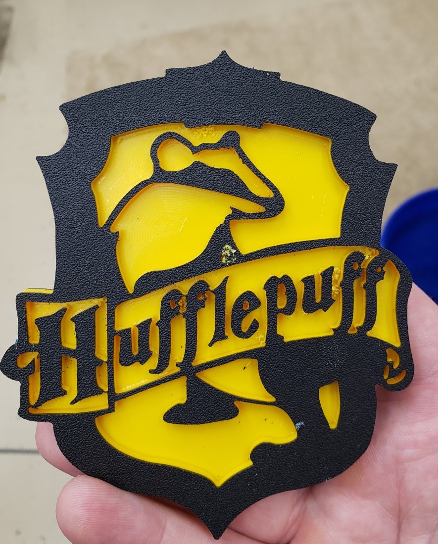
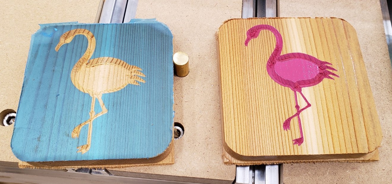
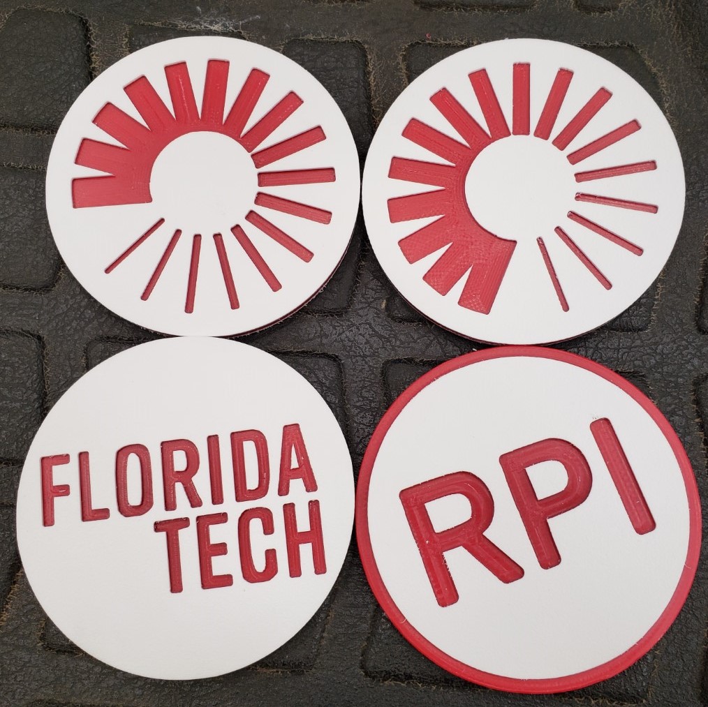
Updates have been few and far between recently. Being a toddler parent doesn’t afford me a lot of time in the shop, and the learning curve has been steep on the mill. That said, I have gotten a lot craftier with it and have fusion 360’s complicated CAM system pretty well whipped. I built a set of drawers for my mill and in the process created multiple versions of a joinery jig, and even dove into python code to post process my g-code. It will take a few posts to unravel it all. First up, a few shots of random fun coasters I made the past few months.
The Drawers

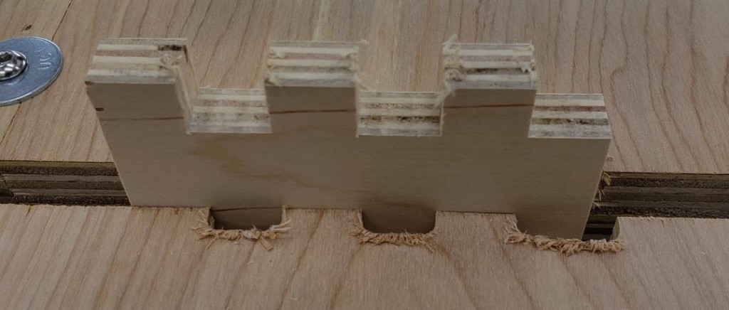
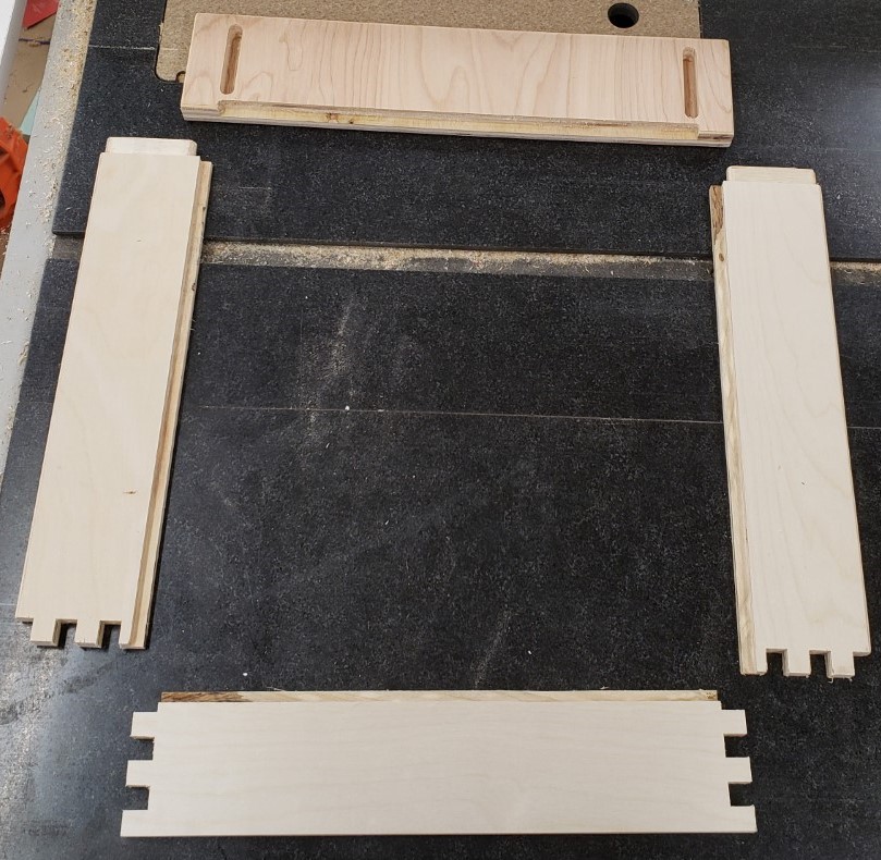
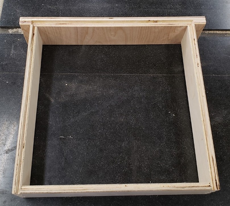
What kind of drawers are we talking here? Nothing too fancy, but I wanted the ability to make finger joints without too much fuss and setup. I’ll leave the details of the joinery and lessons learned for another post. For now, this one has finger joints on the back, and a tenon into the drawer front for the sides. Hidden and very strong.
Jig V1

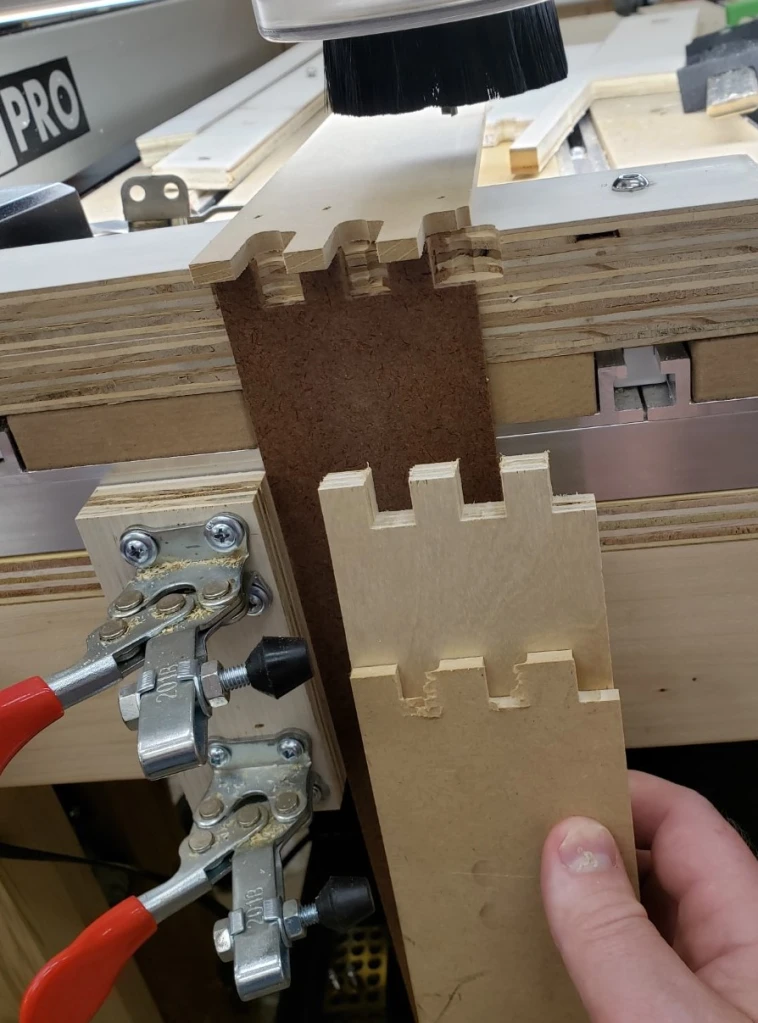
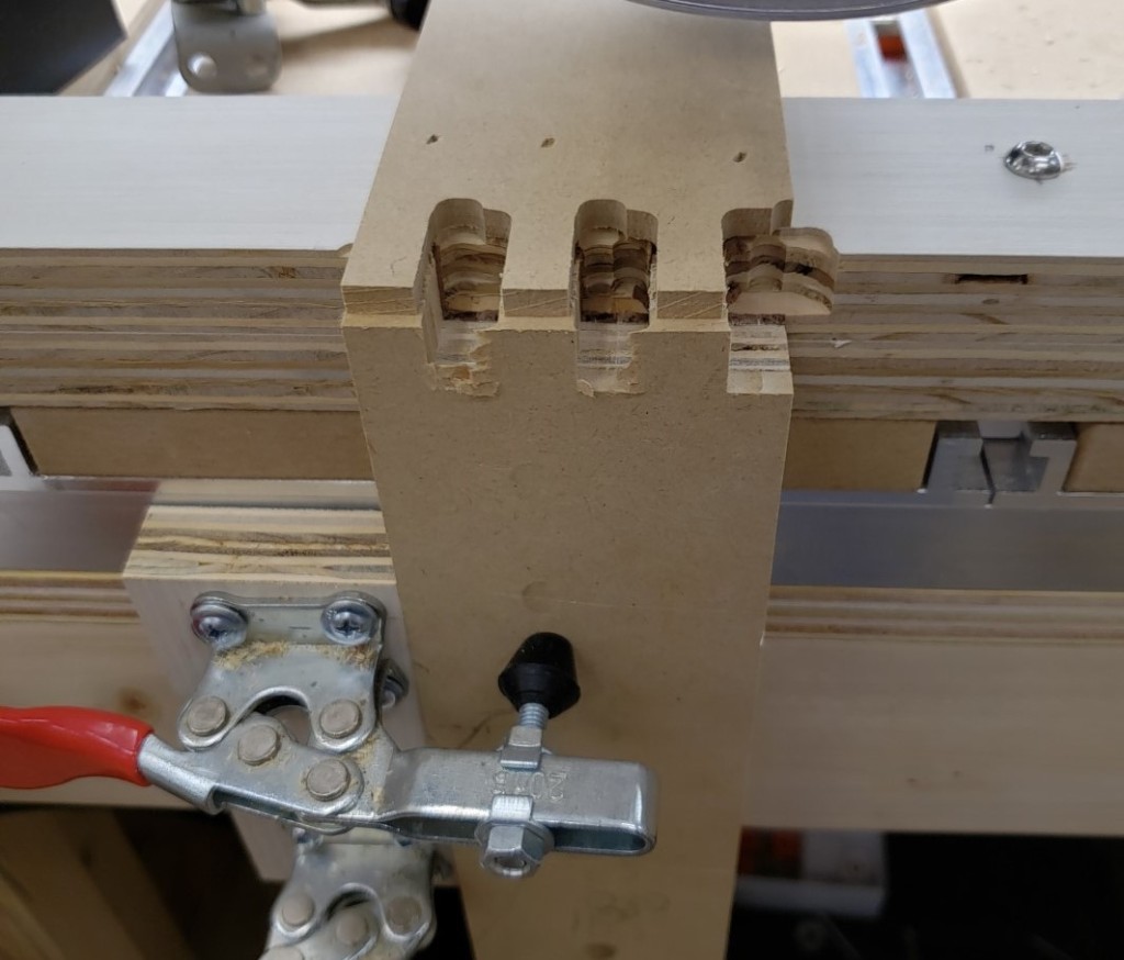
The first jig was a pretty simple setup. I attached a piece of plywood to the front of the mill table to align boards vertically to the table. It was square to the top and had cam lock clamps to hold the board in place. Sticky backed sandpaper provided secure grip on the table side and on a clamp board. I had a double layer of plywood screwed down to the table behind the board to back the cut and a plank of 1/4″ MDF on the font. This gave both sides of the cut support to prevent blowing out any drawer side pieces.
Clamped side in place

With this setup you could repeatably clamp a board in place and usually get a pretty good cut without too much fuss. Replacing the backer was a huge pain, and the top stop was only good for one shape. It worked for my first 3 drawers, but after that I stopped to think of something better.

Joinery Jig V2

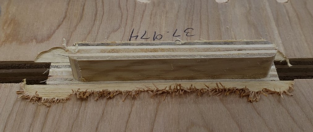
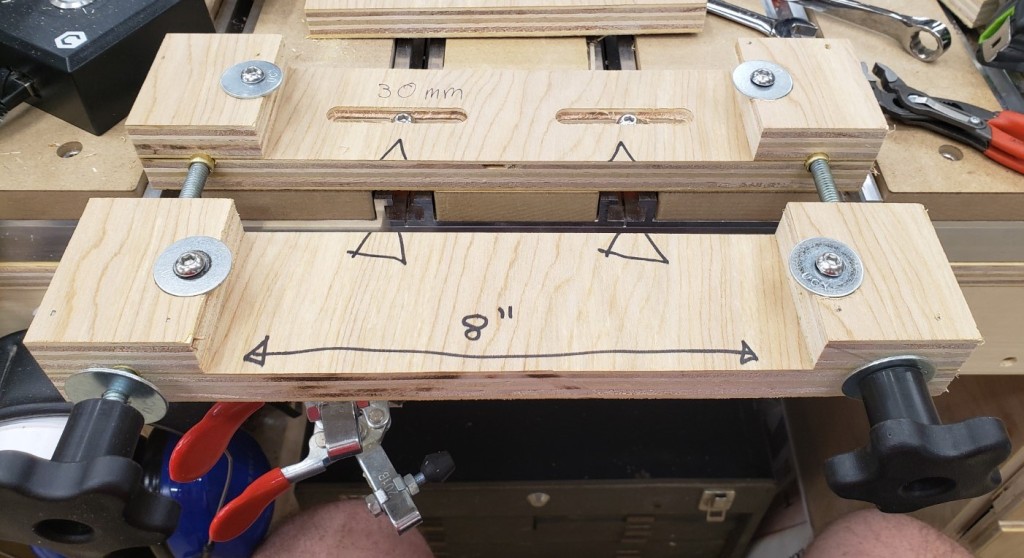
The next version has a two half system. The back half bolts down to the table top while the front half slides and clamps the board to be processed. There are sacrificial inserts that back all of the cuts to prevent blow out. Those are held in place by two clamp bolts on either side.
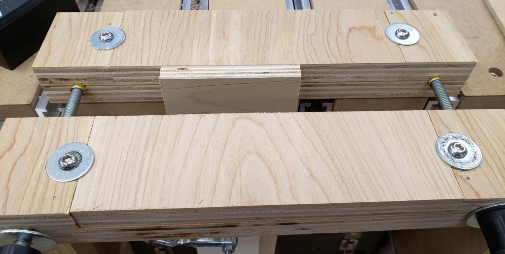
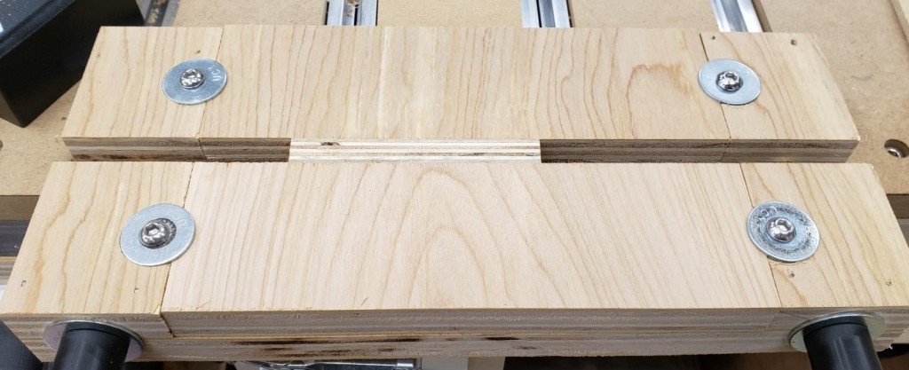
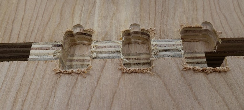
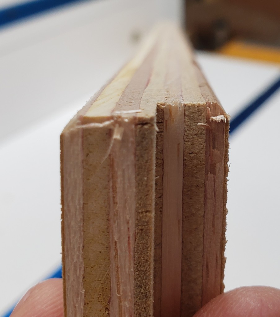
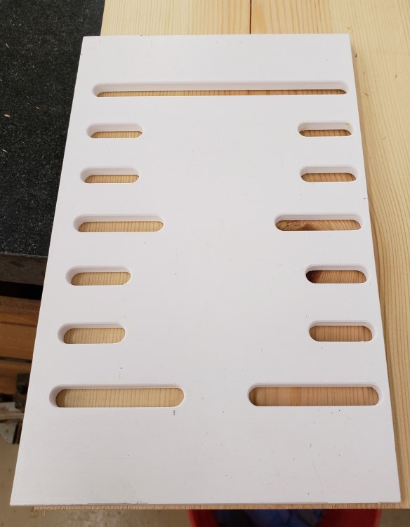
To create the jig I attached two pieces of 34″ plywood to the outside edges of a larger piece of plywood with glue and nails. This would be the base area for the rails/bolts that clamp the two halves together. I will mill it all as one piece and cut it in half at the table saw.
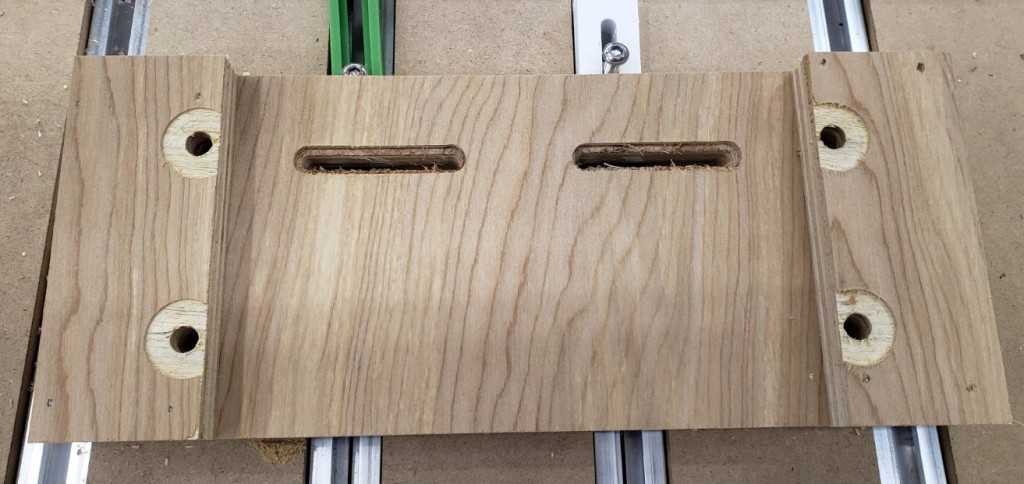
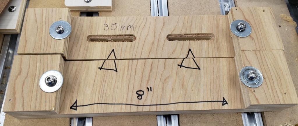
The slots are 50mm long and spaced 100mm apart. That should let me position it anywhere on my table top by always spanning two rails. I started with them just wide enough to hold the bolt head, but eventually widened them to allow washers. Bare screw heads on plywood would eventually compress and allow the jig to rotate.
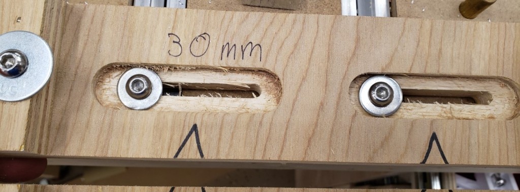
Widened to allow washers

With the milling done, I cut it in half at the table saw, then added some alignment notes. Any 8″ wide piece of 3/4″ plywood or MDF should clamp in there.
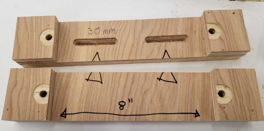
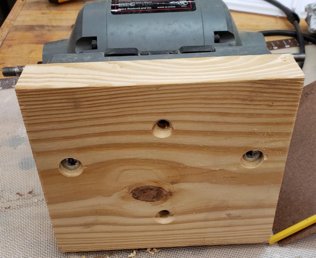
To hold the sacrificial waste blocks I screwed in an M6 threaded insert to the bottom of the jig. Button head screws and fender washers sit in the counterbore and clamp down the waste boards.
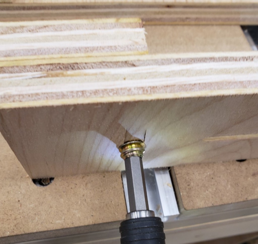
I clamped the boards together and drilled all the way through with a 3/8″ bit. It gave clearance for a 5/16″ t-bolt hammered into the back, and brass tubing in the remaining spaces. This acts as a bushing for the 5/16″ bolt. I used thread locker to keep it secure in the back, then large knobs in the front to clamp everything down.
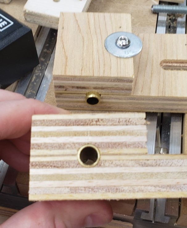
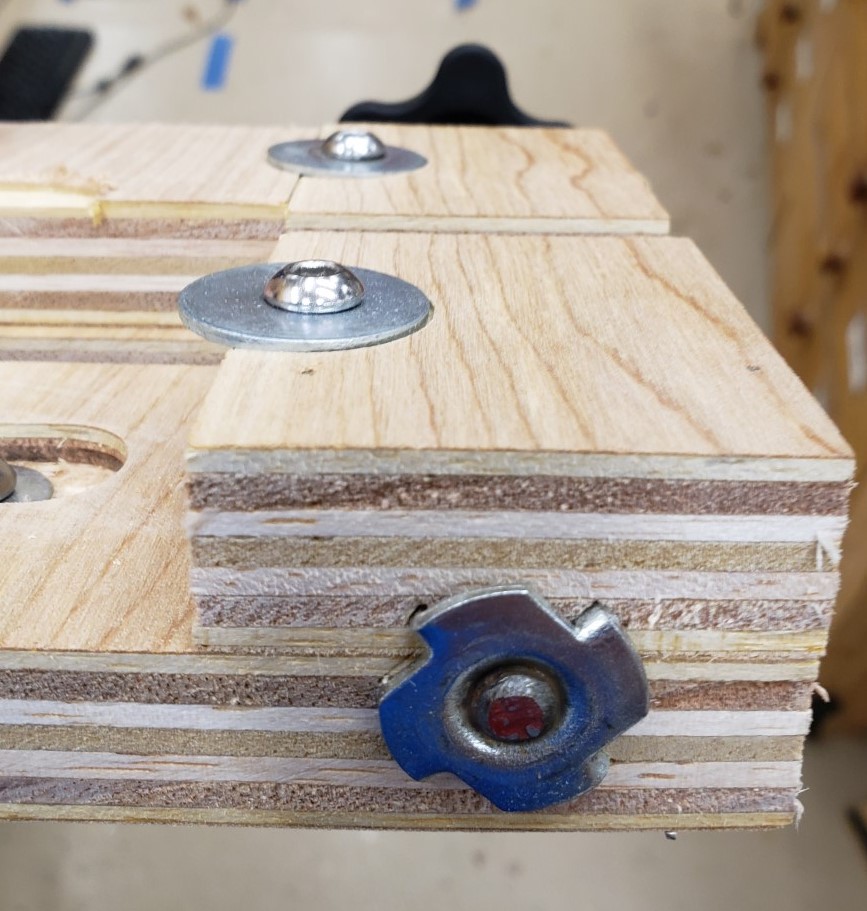
T-nut secures 5/16″ threaded rod

Here it is fully installed without the waste boards inserted yet. You should be able to get at least 2 uses out of a 3″ wide waste board by flipping it around after the first cut pattern. I found mine were in good shape even after making 16 cuts of the finger joint pattern.

This version doesn’t need the cam clamps, the vise like action of the two threaded screws has plenty of clamping power. Similarly, I didn’t need a height stop. I could very accurately feel when the board was flush with the top of the jig. The second round of drawers went very smoothly with this jig!

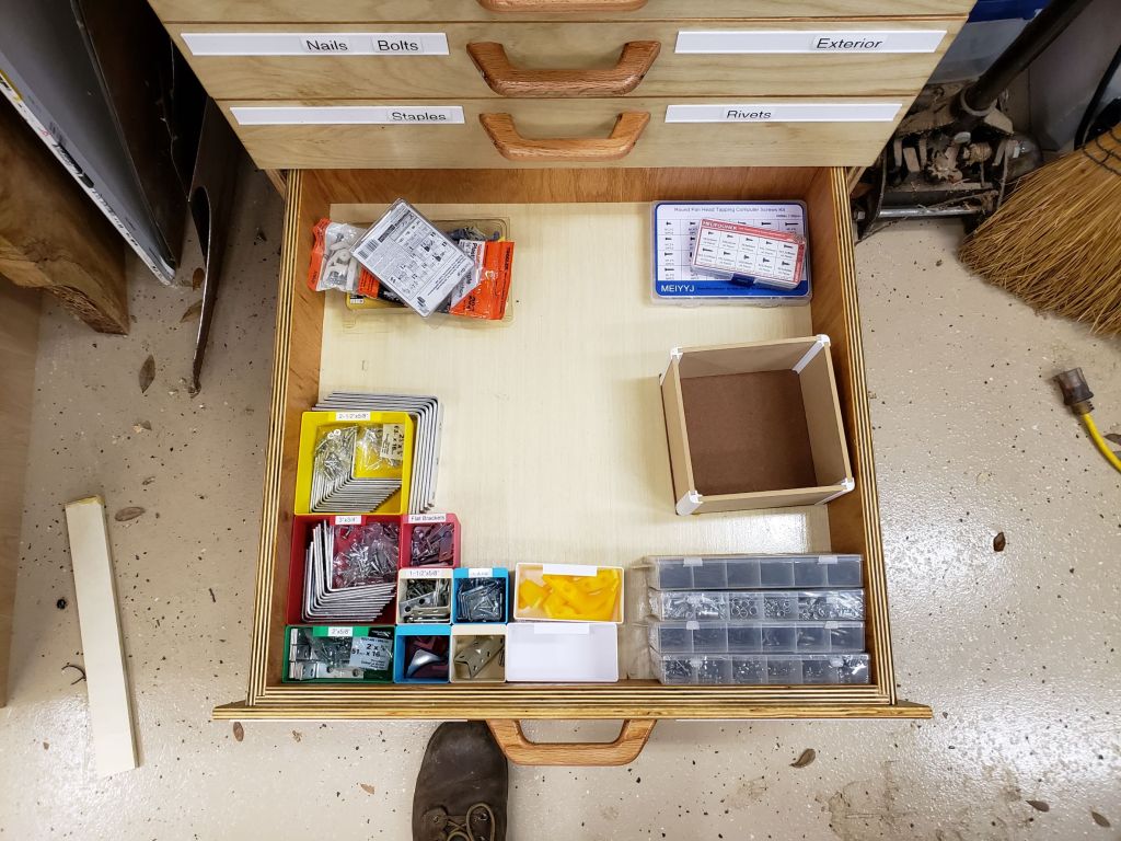
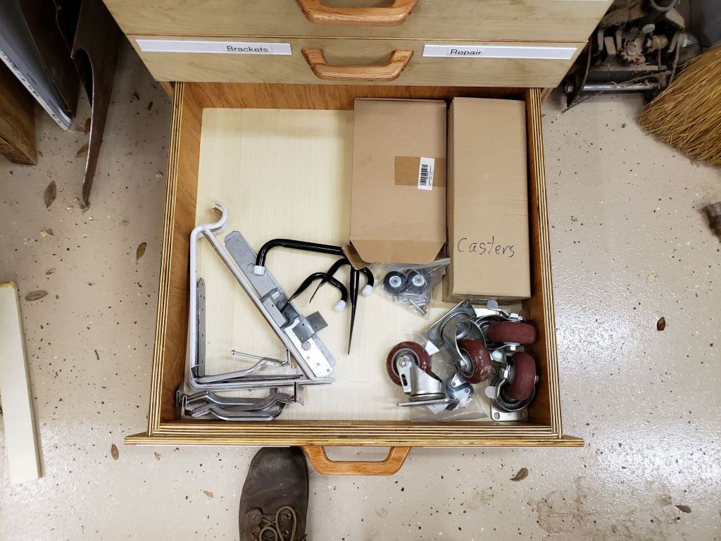
Materials Cabinet

In industry there is a line of drawer cabinets from a company called Vidmar. They can be short or tall, but are usually pretty wide and deep and super well built. Each drawer can hold hundreds of pounds, they have different divider systems, and full extension drawers. Also they tend to have fancy features that don’t let you pull out too many drawers. You could easily tip one over on yourself and cause serious injury.

In looking at my materials storage area, I have a lot of plastic bins that are organized, but maybe only half full. I have made hardware drawers in the past and love their organization and dense storage capacity. This new cabinet will be much larger and deeper and use full extension metal slides. I started with a lot of planning. I wanted to maximize the materials I used, my limited shop time, and the space available.

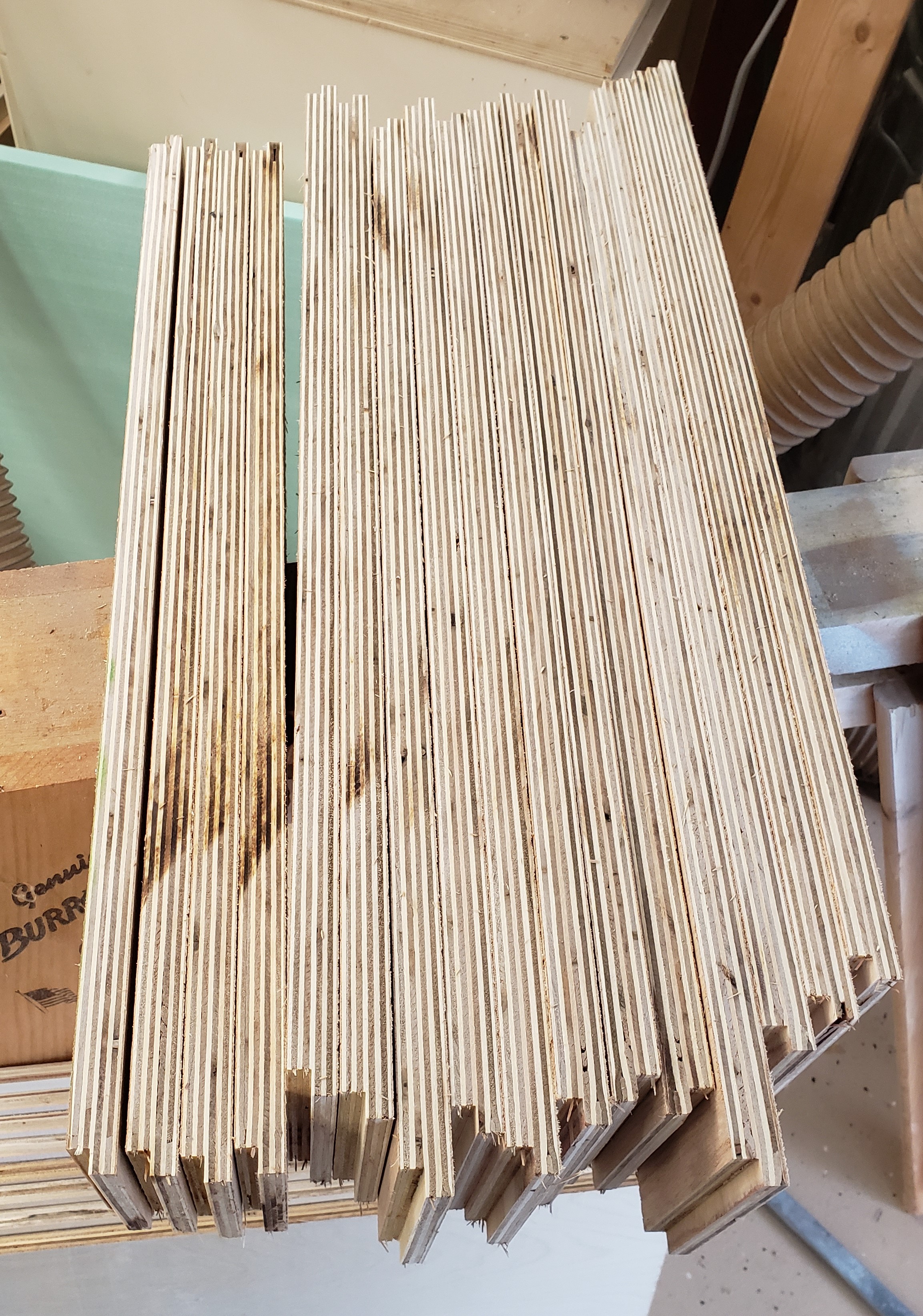
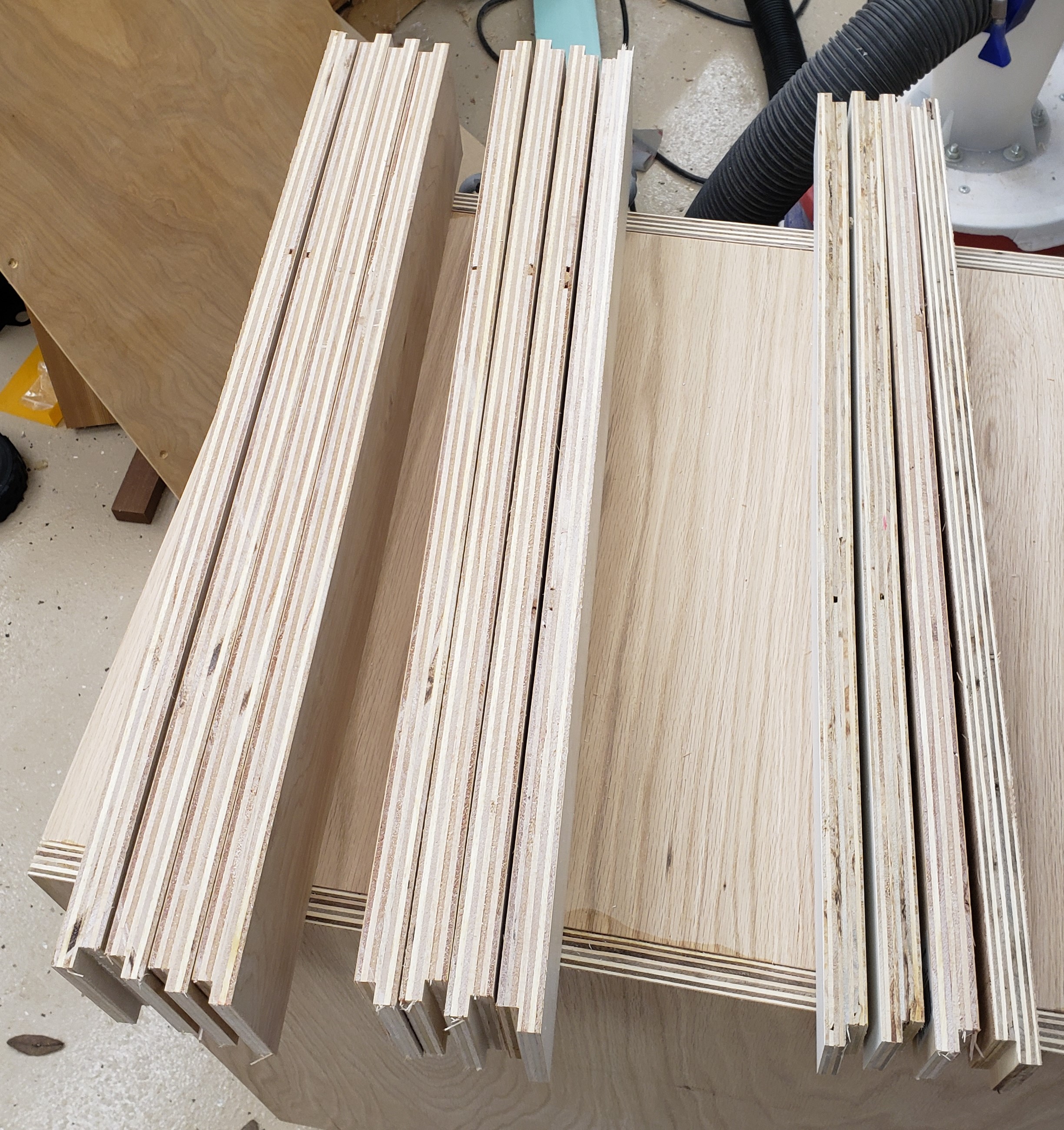
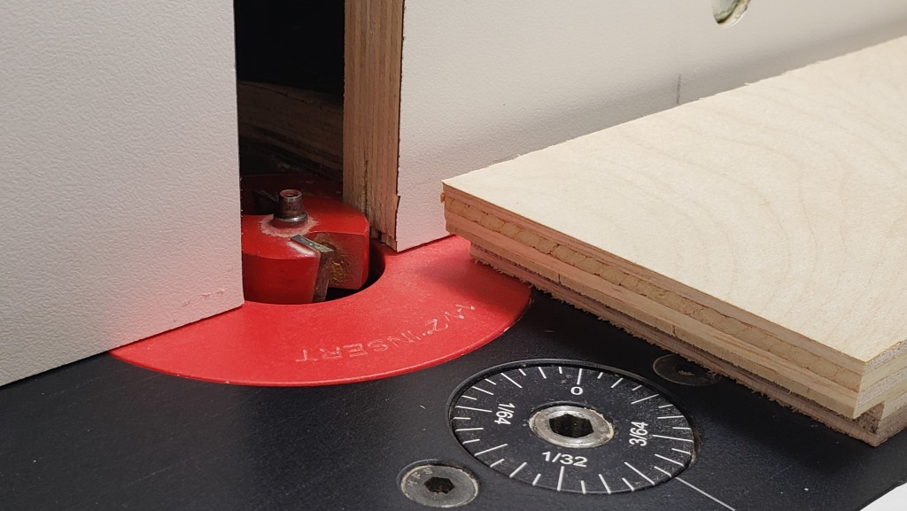
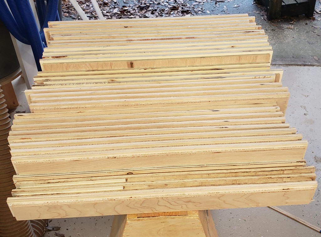
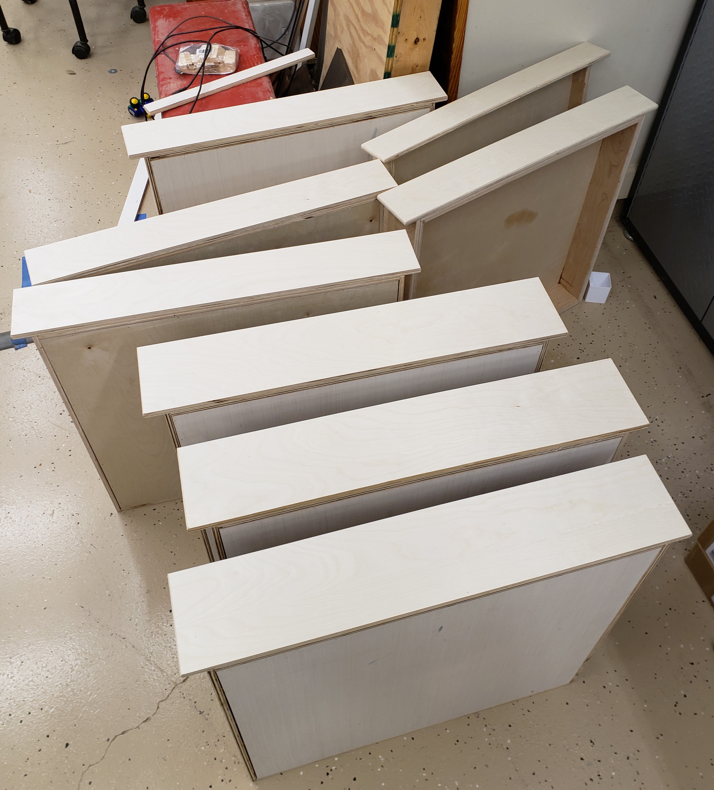
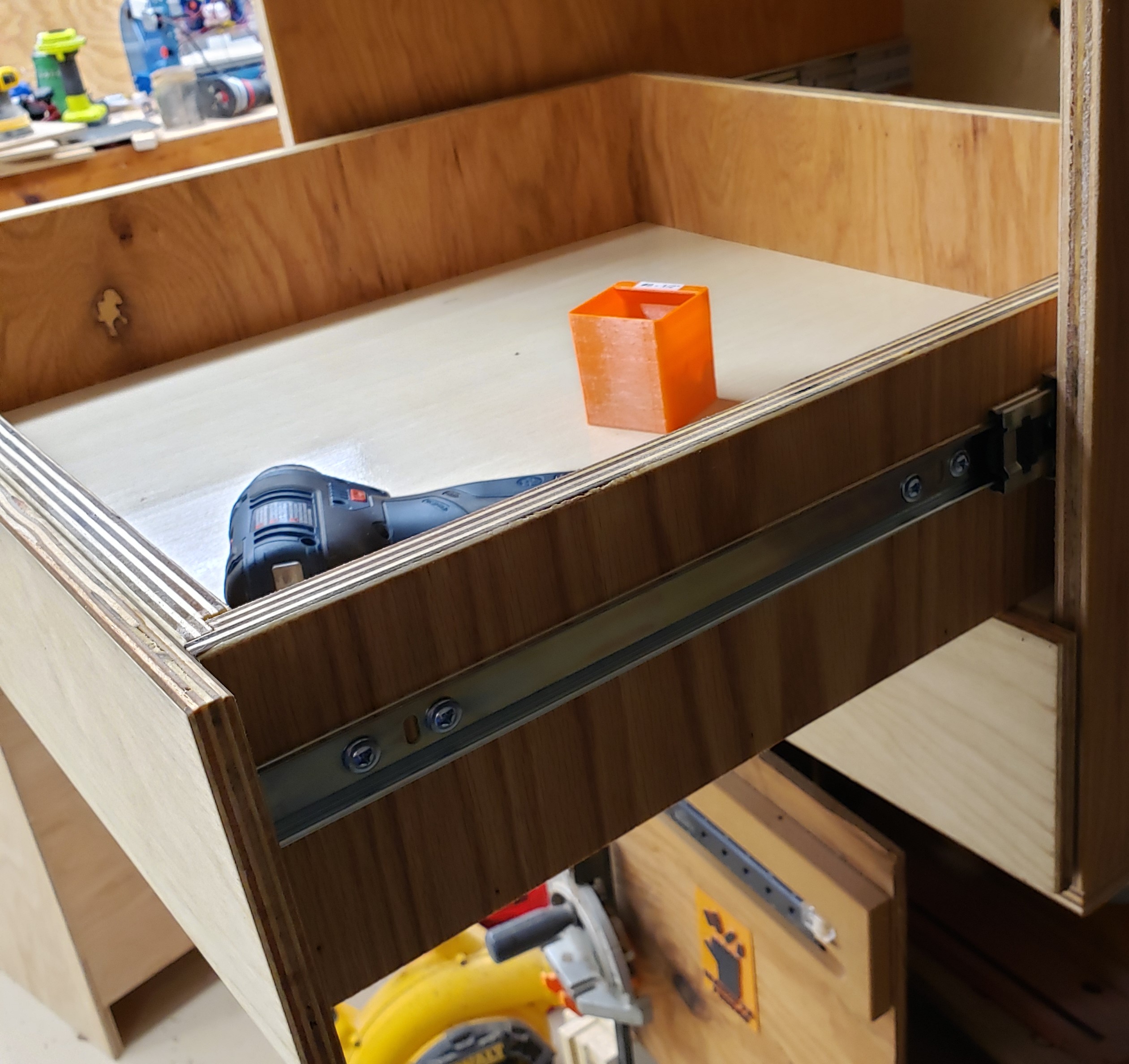
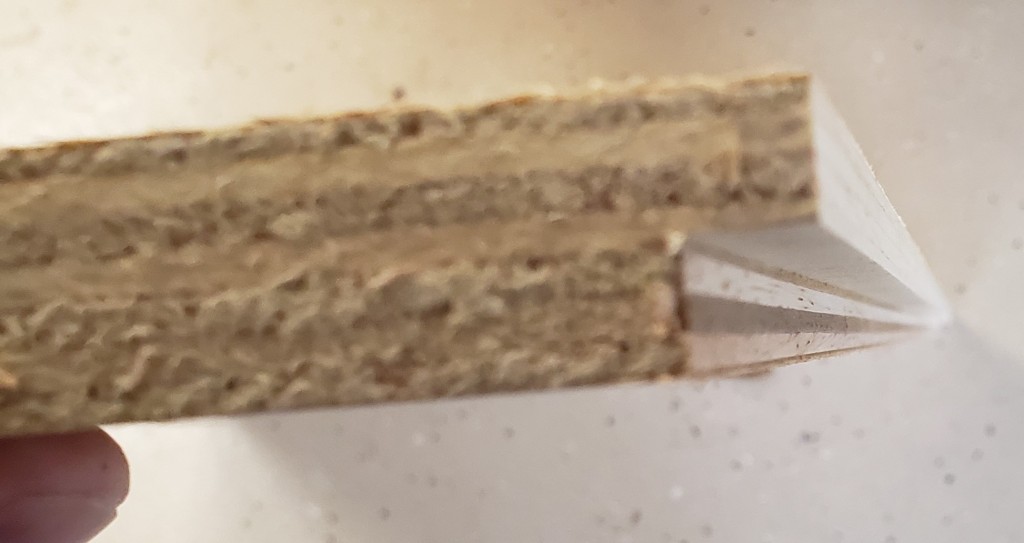
I had it all worked out on paper, and started with the drawers. I cut 24″ wide sheets of 3/4″ plywood and put a rabbet down two sides to make half lap drawers. All four sides of the drawers would all be the same length. This made batching easier. Routing bulk material was faster and cleaner than cutting out individual sides, then doing the routing. This was a big improvement over previous drawer efforts.

Rabbet for the half lap

With all the sides cut, I put another rabbet along the bottom of each board for the drawer bottom. Each would get a 1/2″ piece of plywood in the recess. Probably overkill, but I want them to be able to handle a lot of weight. Eight 24×24″ drawer bottoms worked out nicely to 1 full sheet of 1/2″ ply. It was subtle, but I put a little radius on the top edges of all the drawer sides to make it easier on your hands when reaching in. They took a bit of sanding to smooth out.

Routing for drawer bottoms
Slight radius on drawer side top edges
All drawers ready to assemble

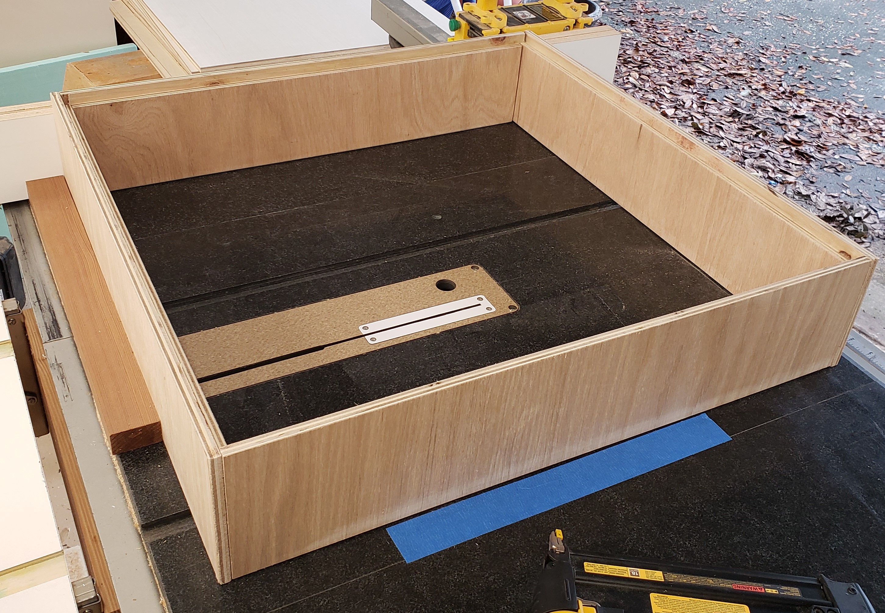
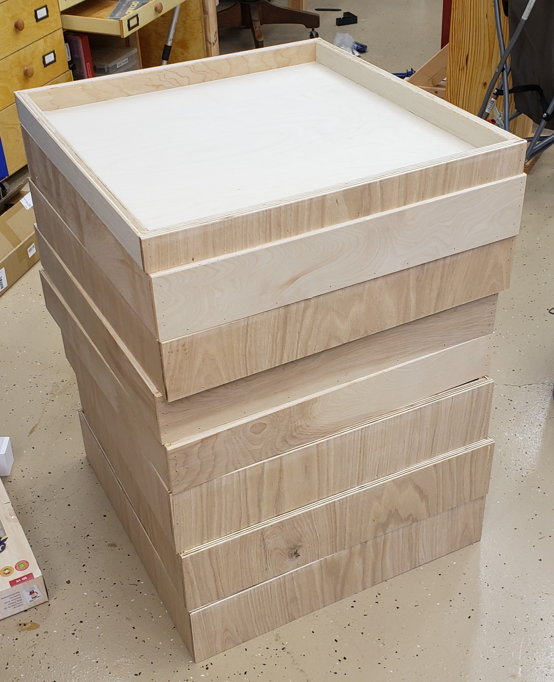
I had everything figured out really precisely, and cut all the drawers at the same time to reduce error. If they went together with any kind of bows or warp, it would throw my plans off. I attached a board to my table saw to act as a square, and used the top as a large flat assembly surface. Each side got glue and nails in two directions. Nailing and gluing a half lap like this is really fast, easy, and strong. The drawer bottoms got glue and nails in from the bottom, and into the side of the bottom plywood. They were fast to assemble, and should be bomb proof!
For the drawer fronts I cut a single strip of 1/2″ plywood and aligned each front with numbers so the grain flows naturally from bottom to top.

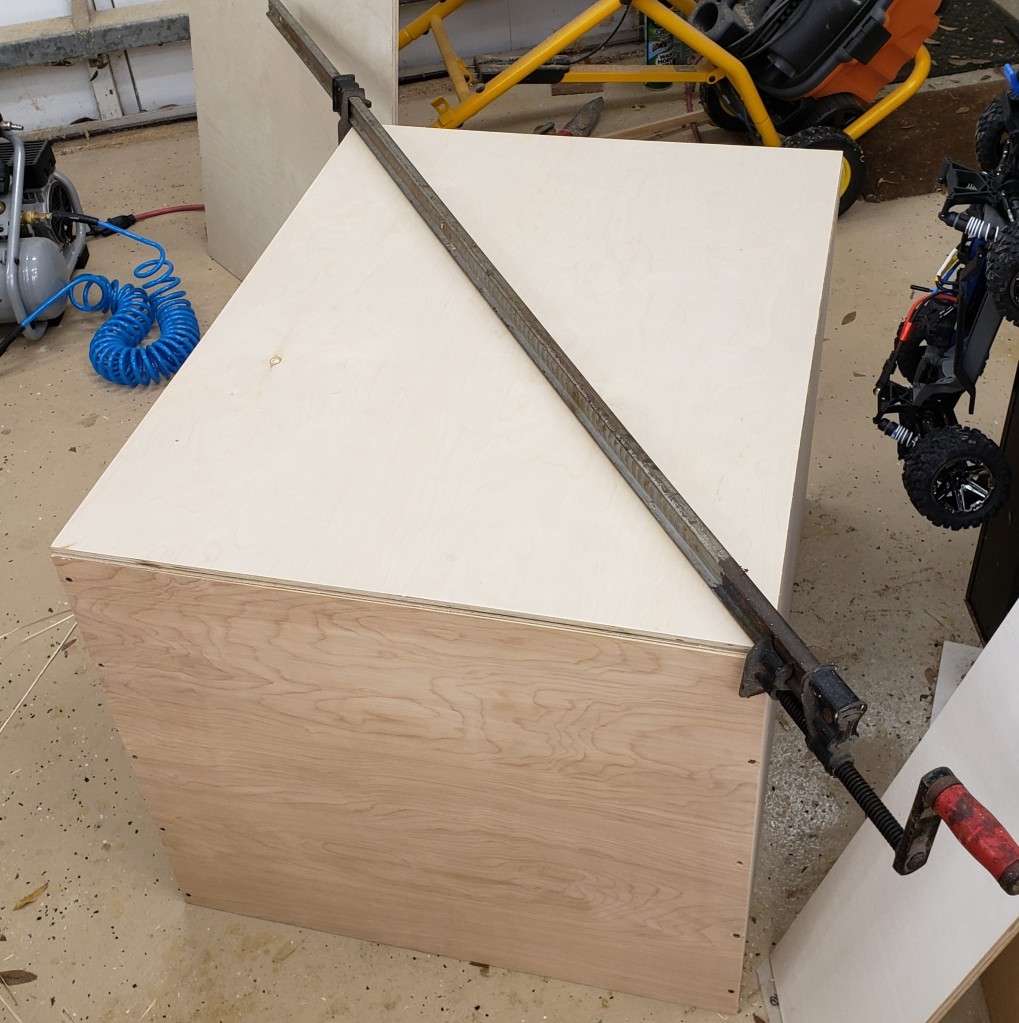
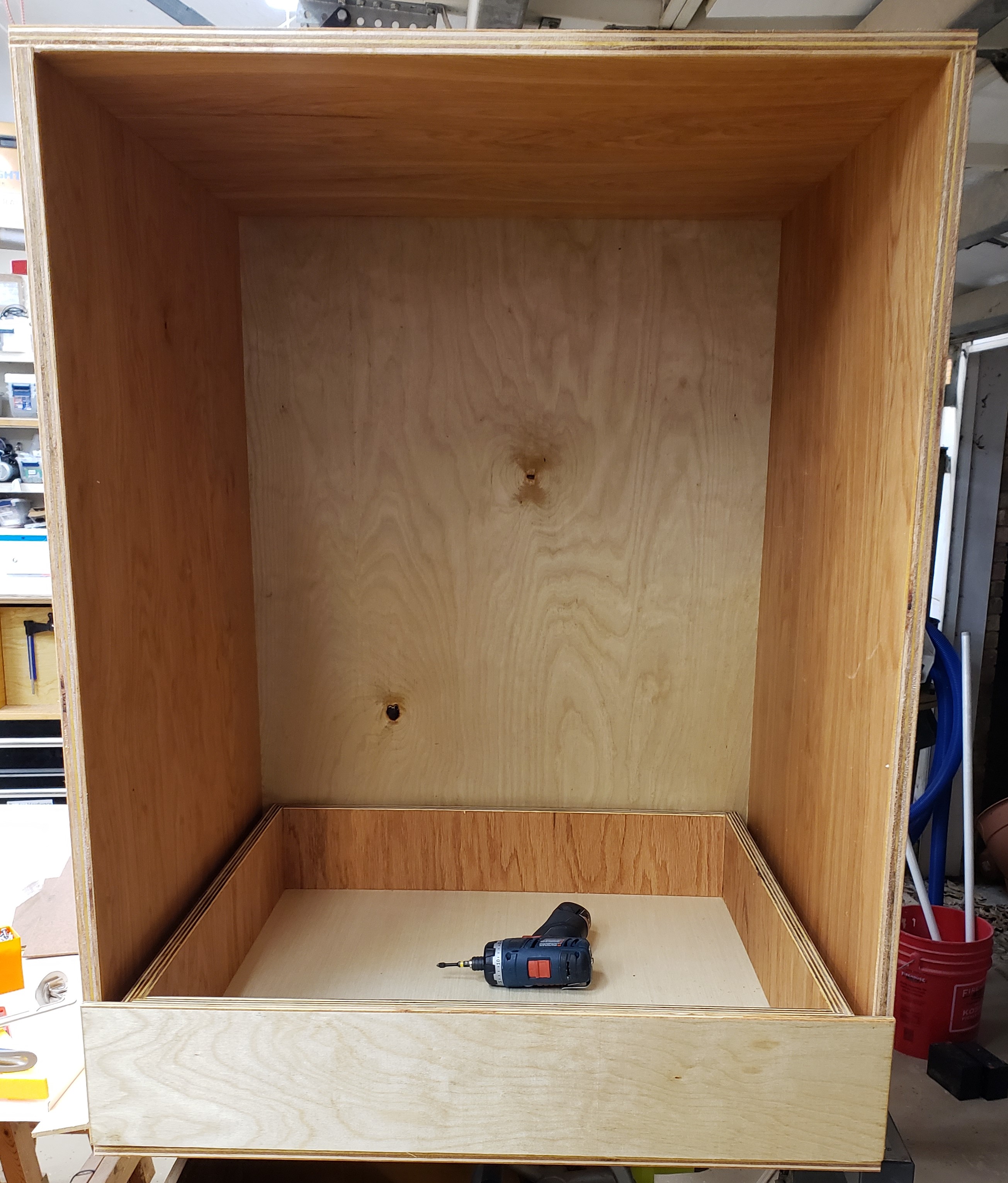
Next came the carcass of the cabinet. Nothing special here, just a box with an open front. I had to be very precise though, if the sides crept in, I couldn’t fit my drawers, and if it got too tall, It wouldn’t fit in the right spot in my garage. I had a little squareness issue, and had to break out my biggest clamp to fix it while installing the back.

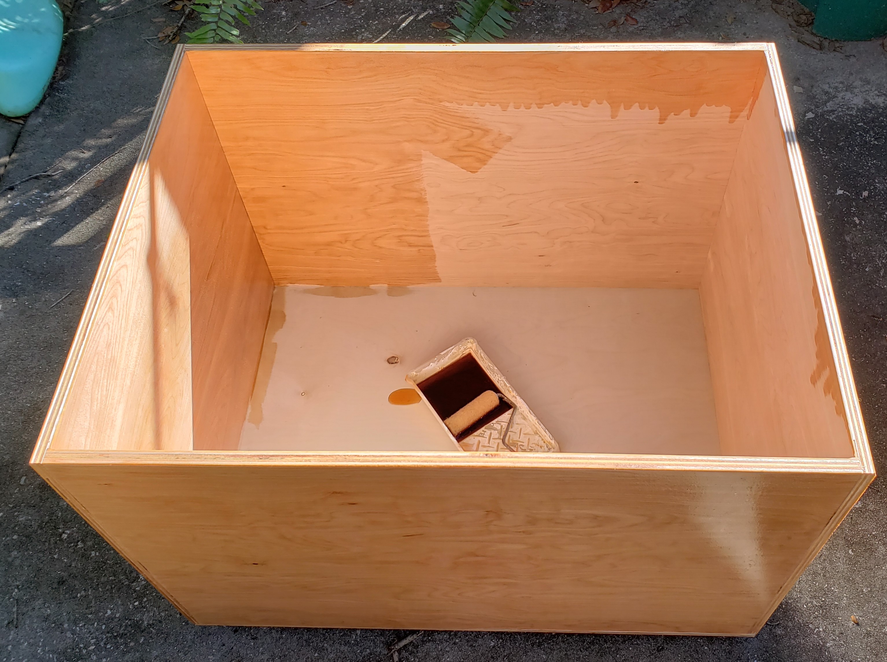
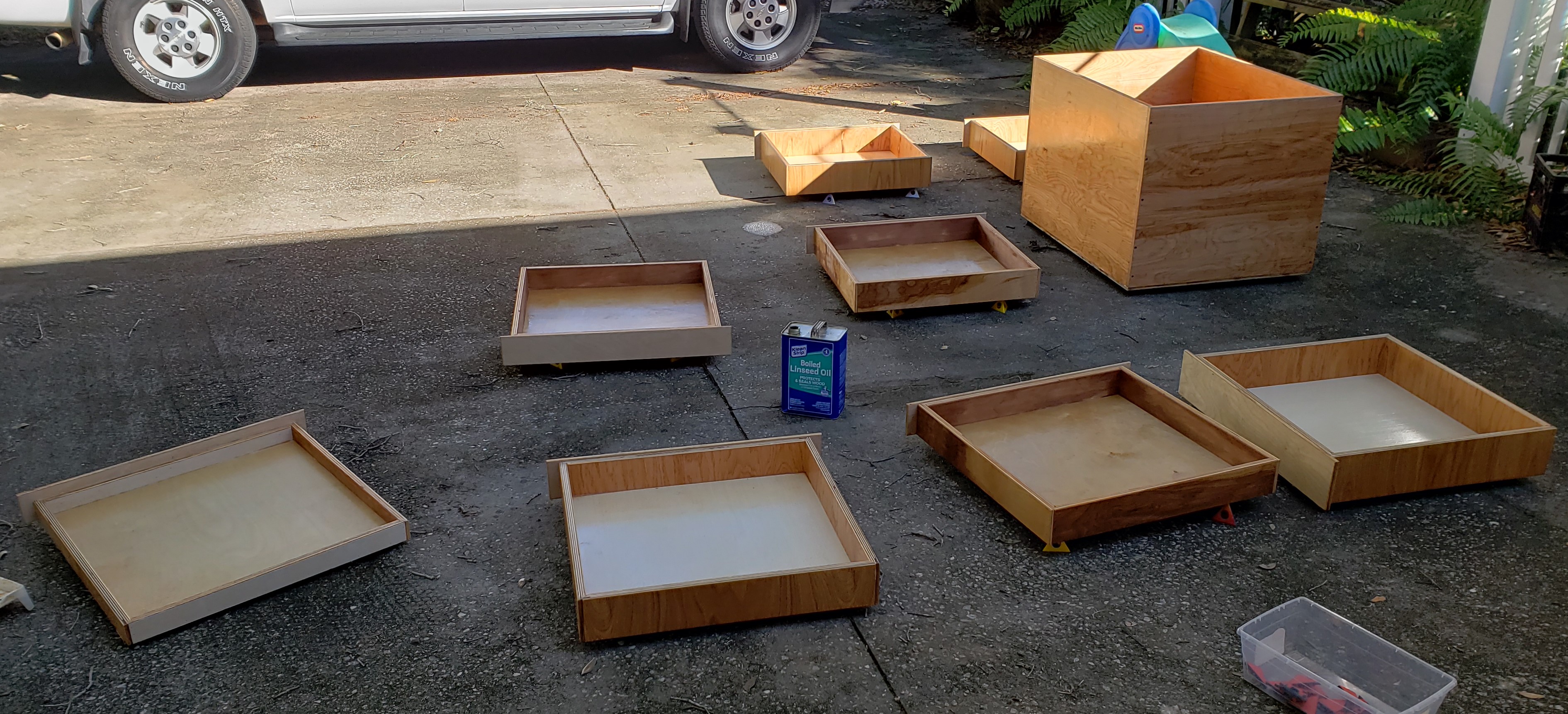
For finish I turned to my usual boiled linseed oil shop tool finish. There was so much to do I broke out a roller and tray to put it all on. I think I went through half a gallon to do the cabinet and drawers. My shop helper was sprinkling the painter pyramids all over the driveway for me to step on.

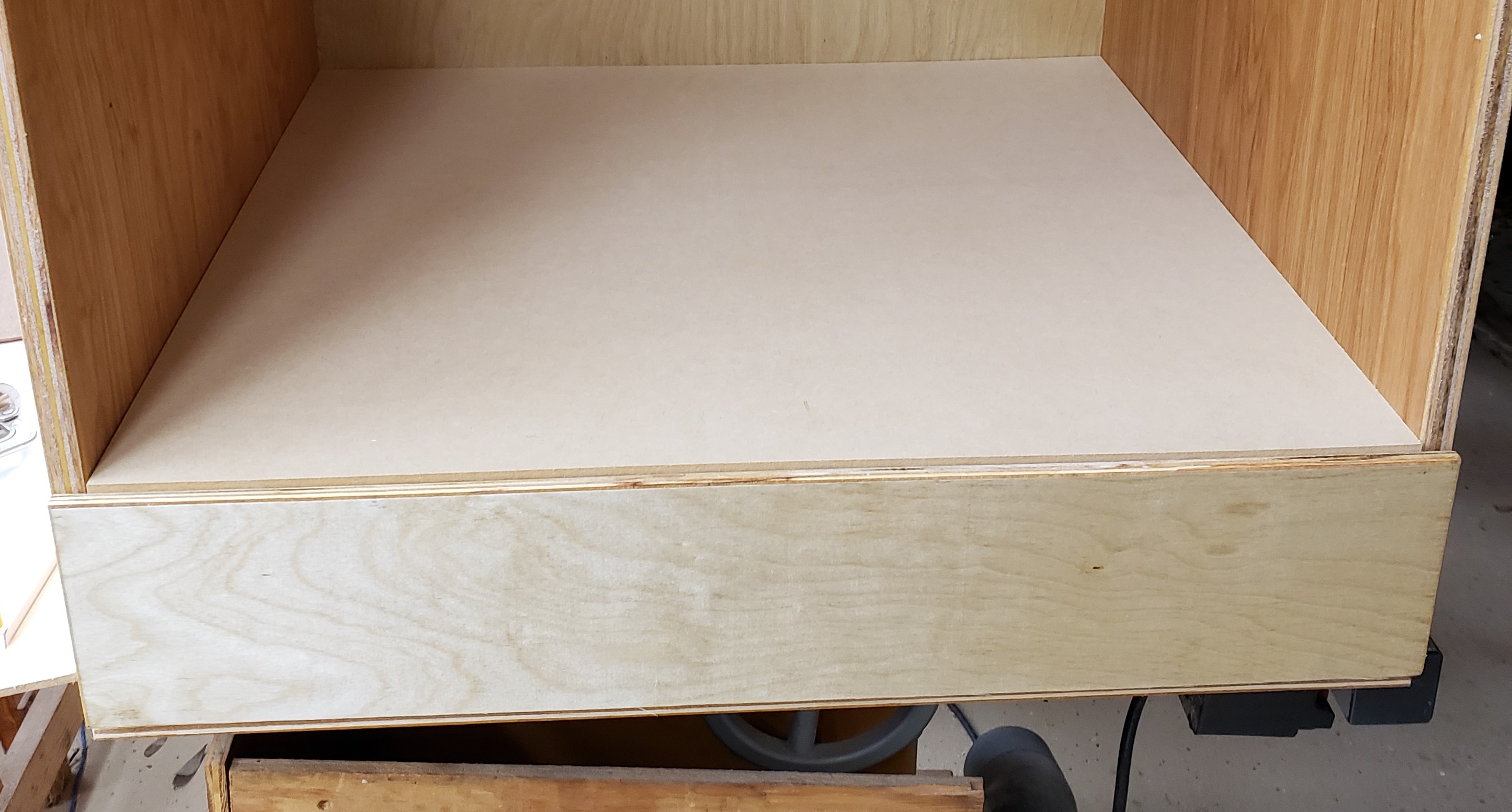
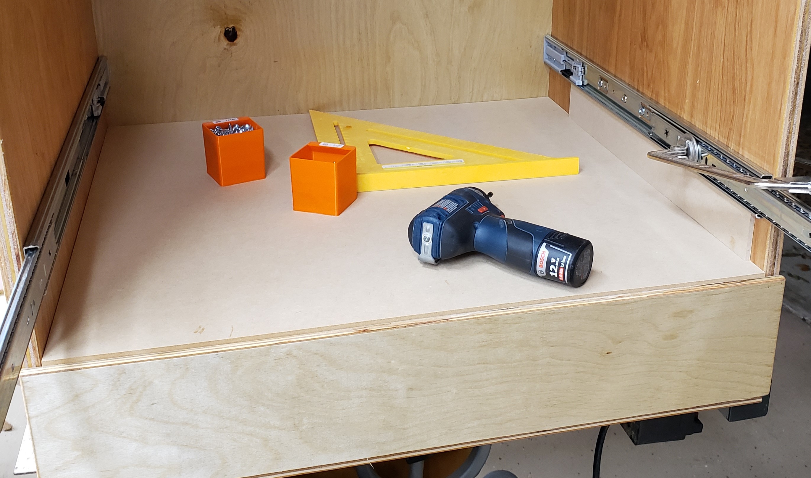
A few days later when it had all stopped smelling I started assembly. The bottom drawer was numbered, and went down with a small spacer between it and the floor. I installed the hinges, then slowly pulled out the drawer and attached the runners. With the first drawer done, I put a 1/2″ sheet of plywood down to provide proper spacing for the next drawer to sit on top of the first. The runners go on the cabinet at a set height, then the next drawer goes in for installation. That gets washed rinsed and repeated until all the drawers are in.

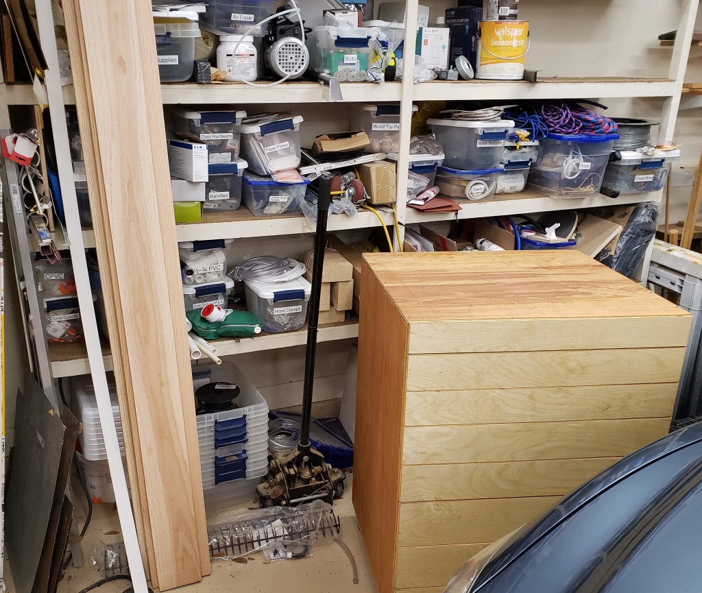
Next comes the home for this big fella. I put heavy casters on the bottom so I could roll it around to clean underneath or rearrange easily. It cost a little storage space, but who wants to bend down that far anyways? Here is the cabinet next to its final resting spot.

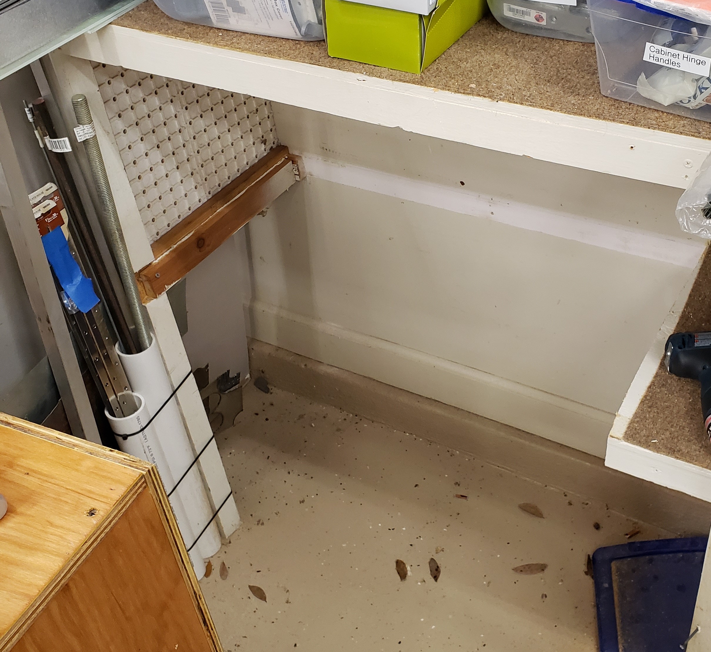
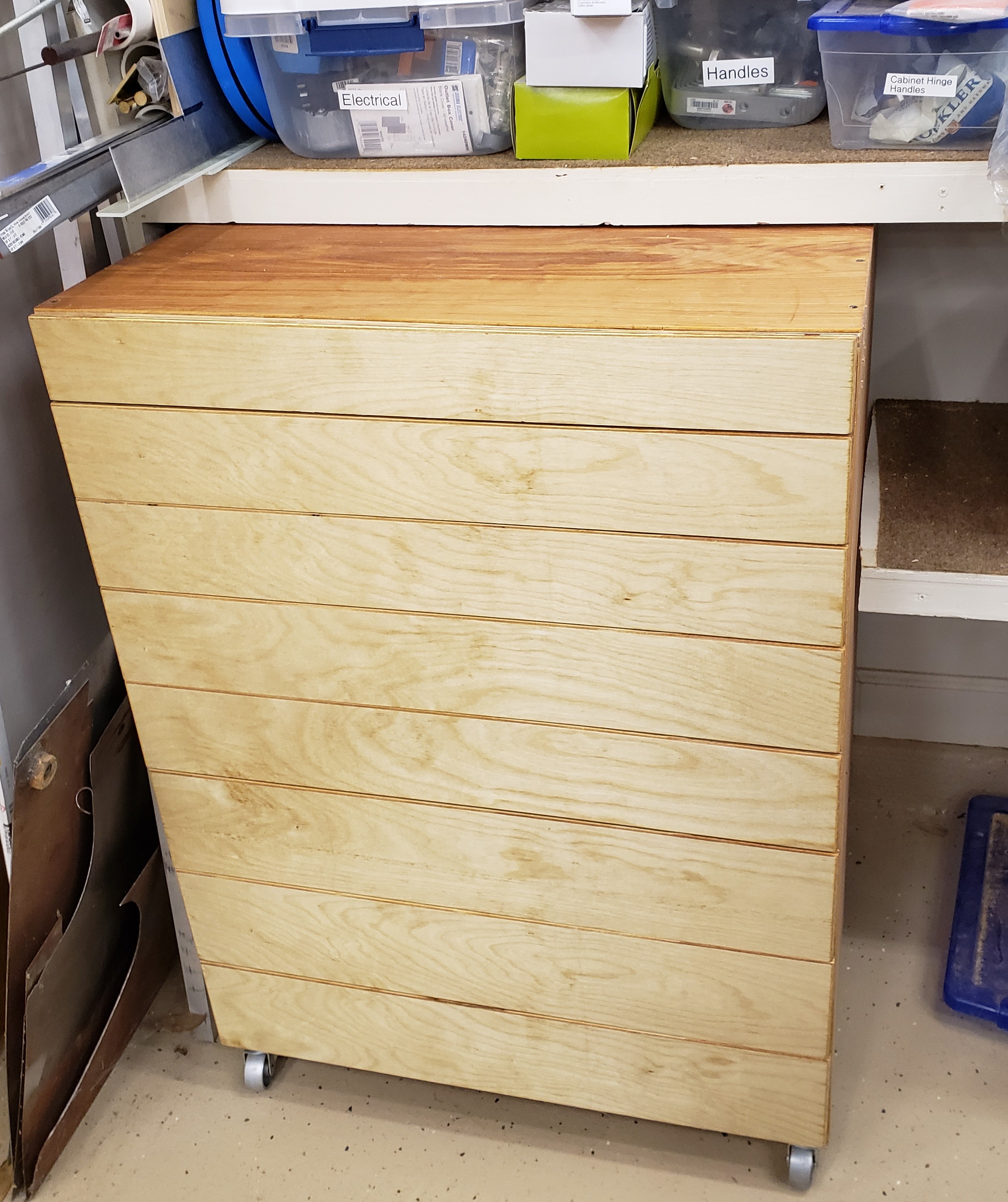
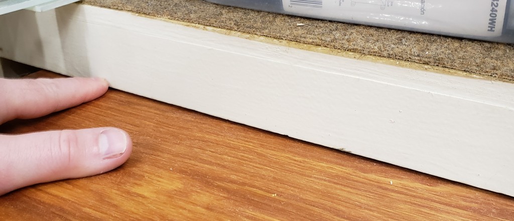
Yes it is a mess, that is why I need this cabinet. I cut out the bottom shelf and slid everything home. I had planned it perfectly. The drawers all fit, the drawer fronts align well, and the cabinet fits up to the next shelf with only a tiny bit to spare.

Gap between the top of the cabinet and the next shelf. Less than 1/8″

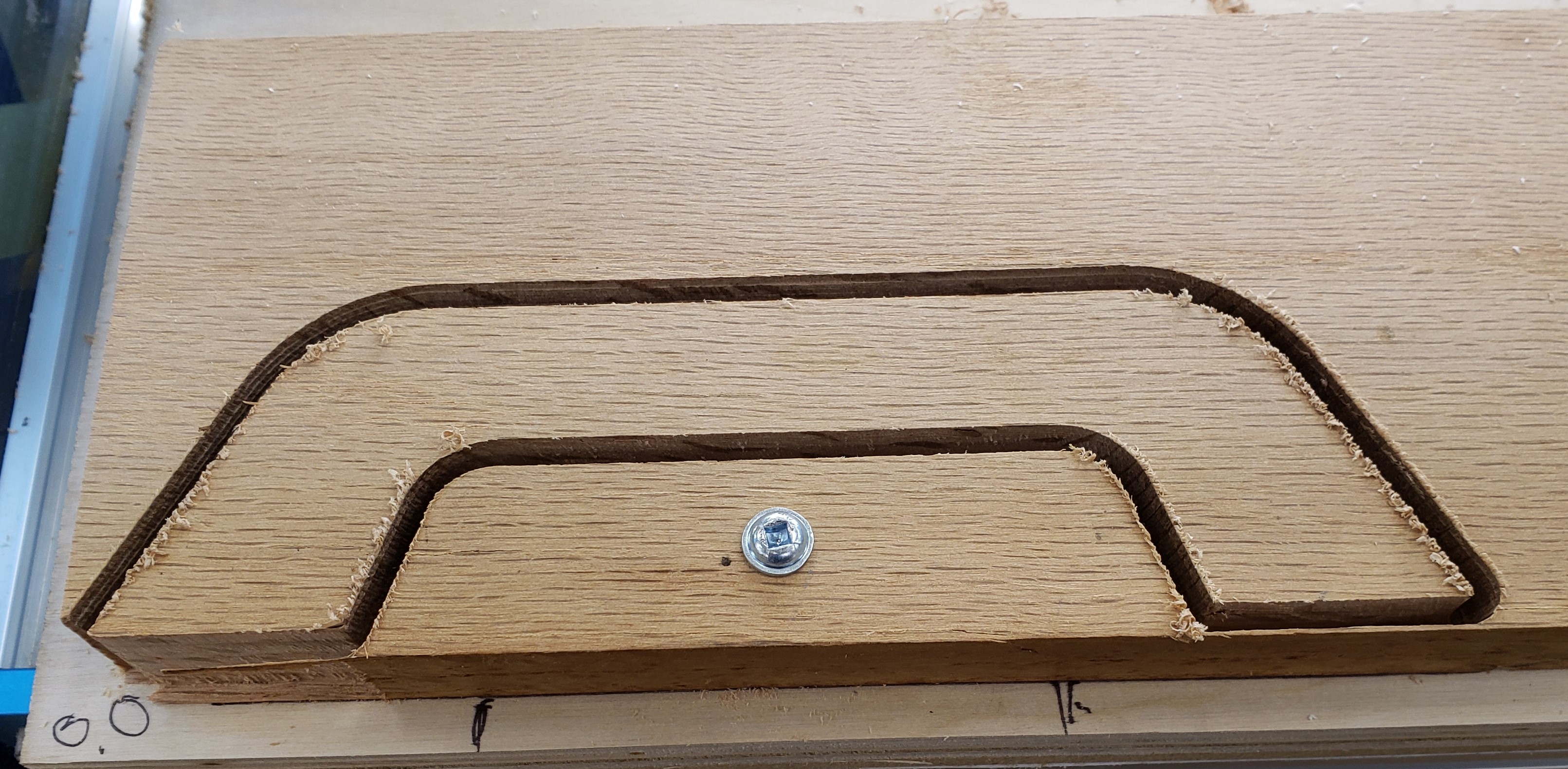
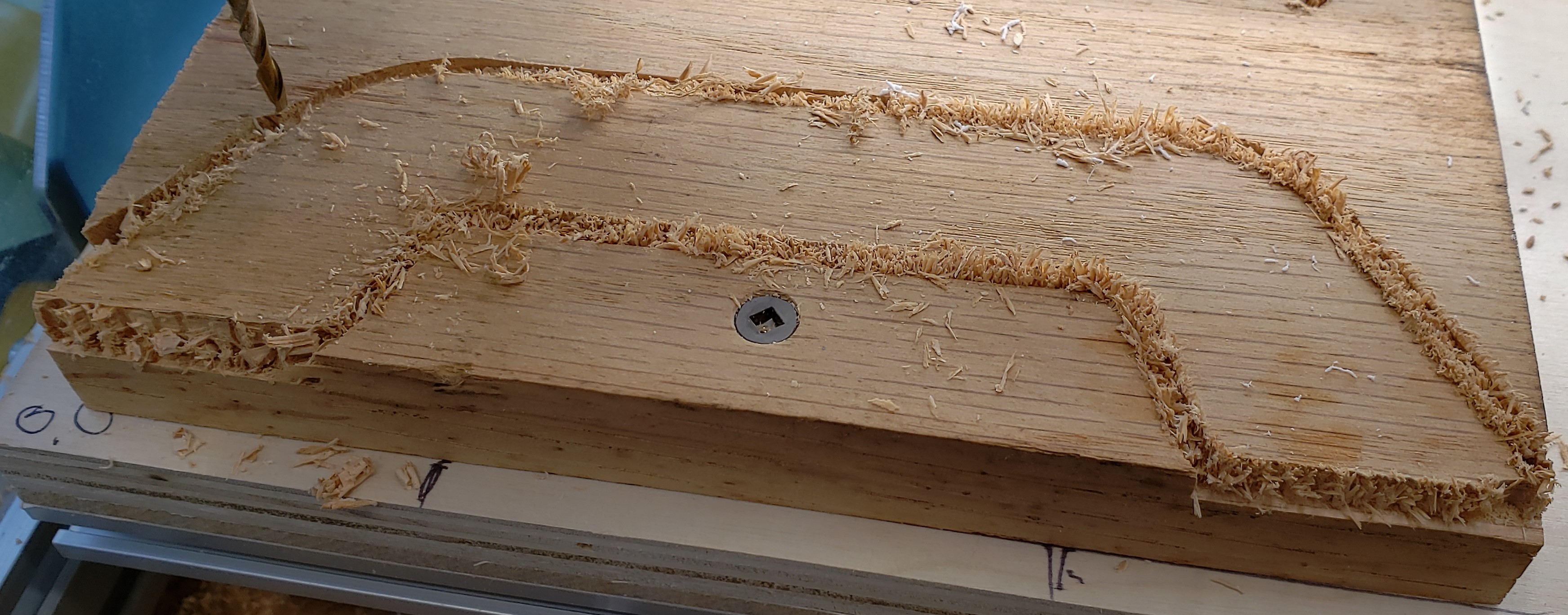
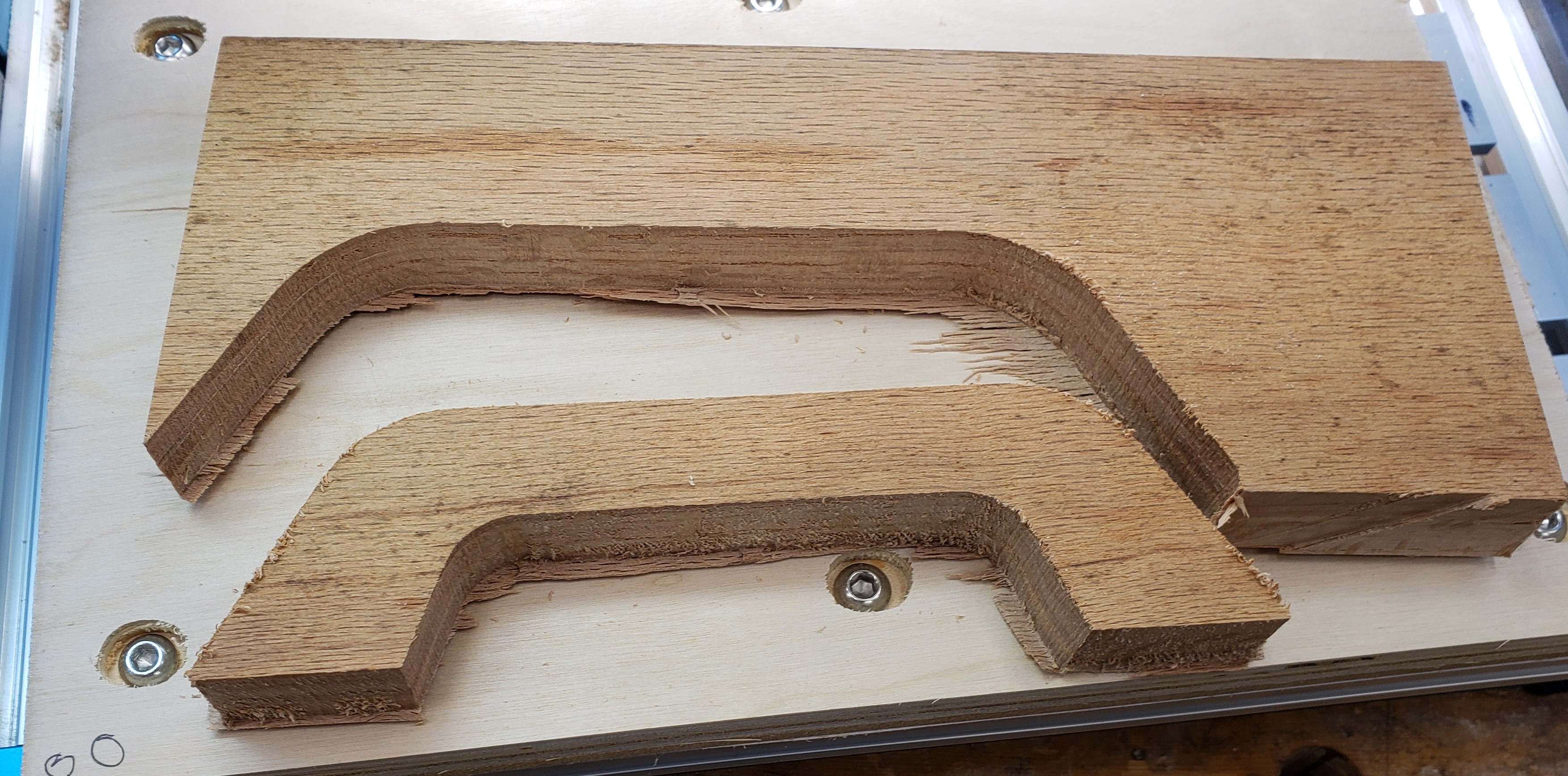
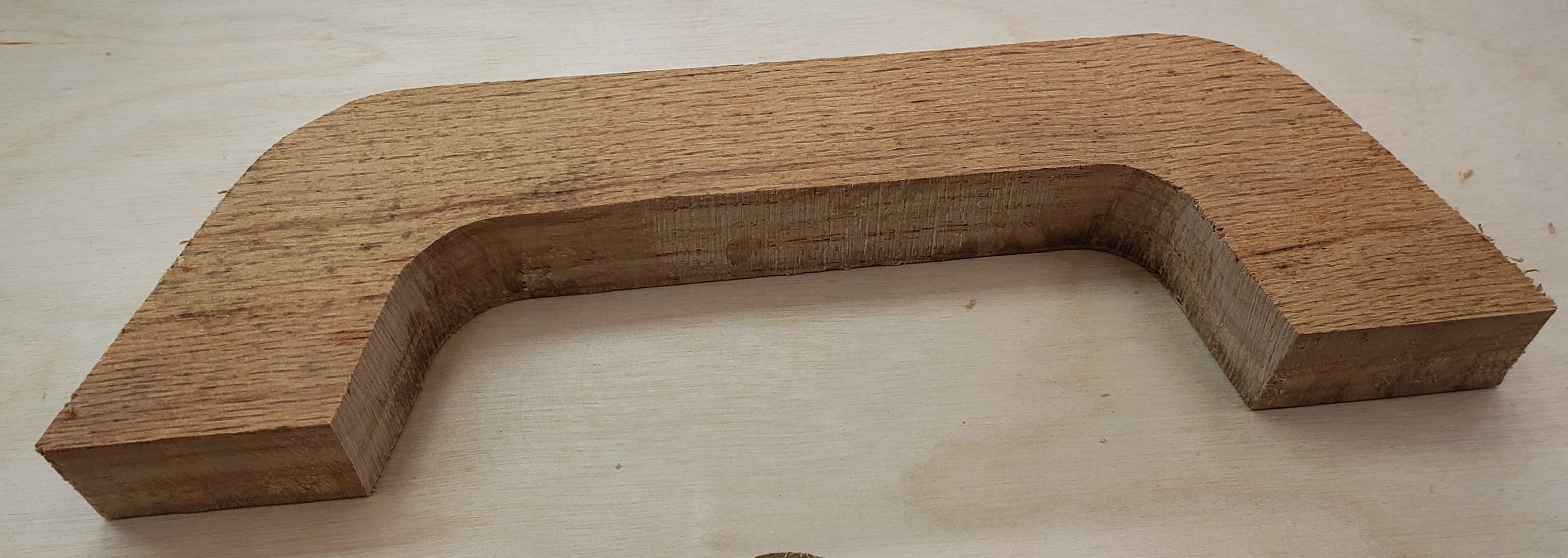
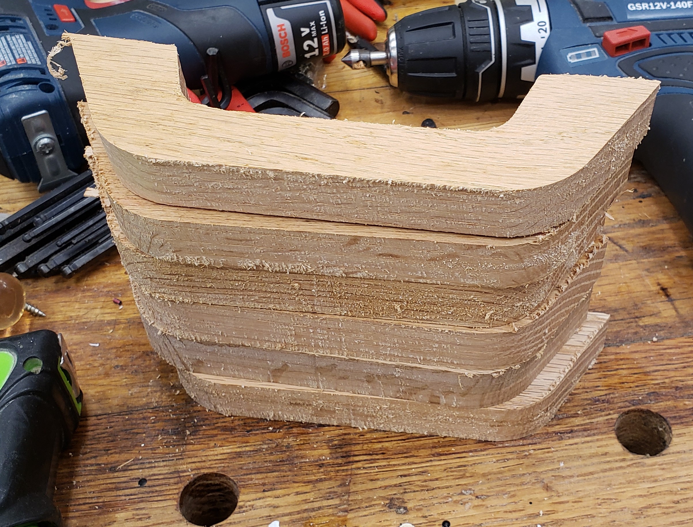
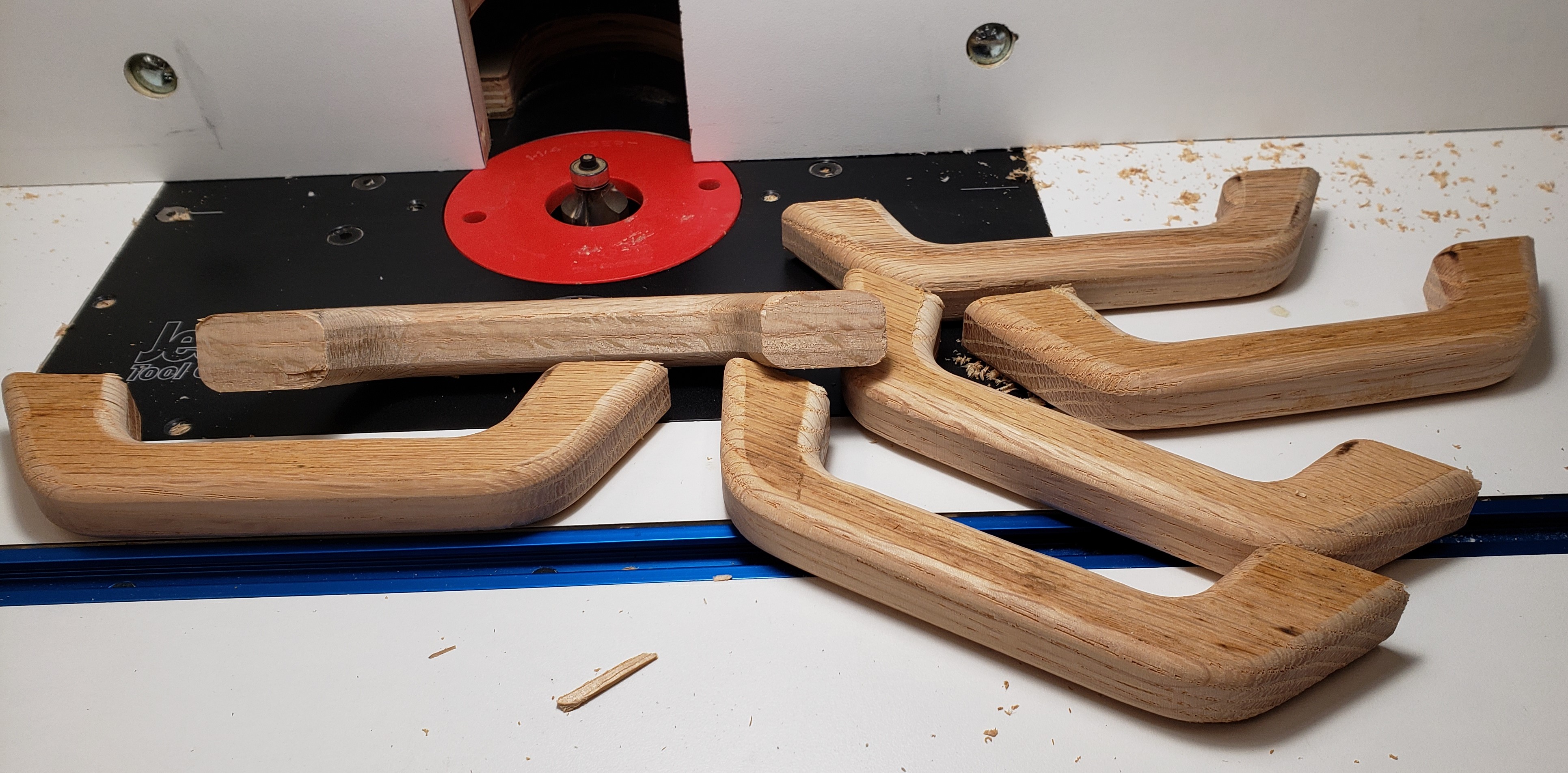
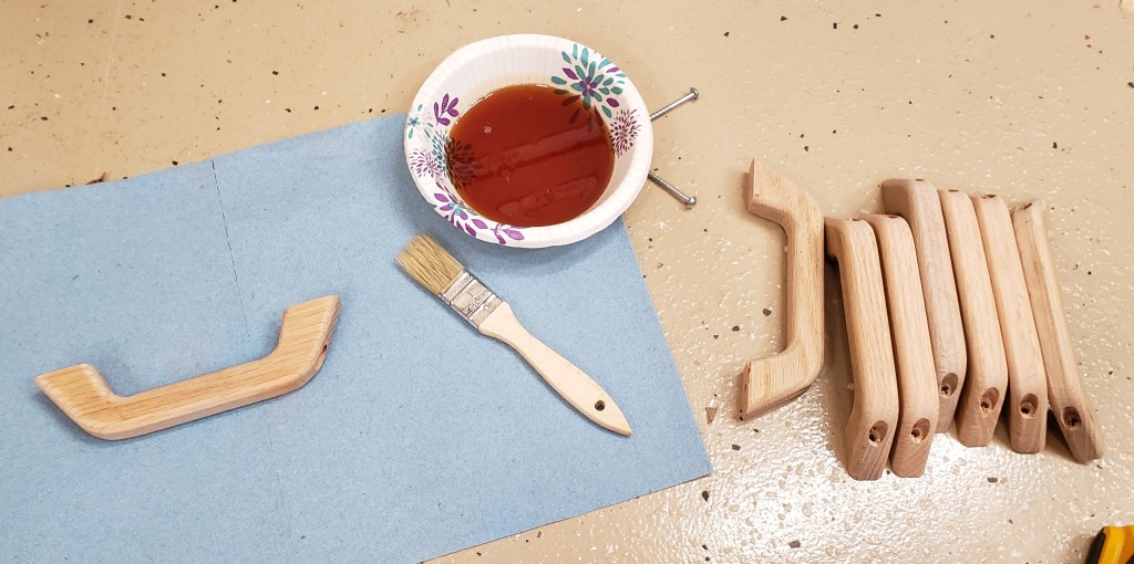
Drawers of this size need a good beefy handle. I employed my mill to cut a nice looking handle shape. It was a bit more of an ordeal than I thought it would be. The machine really bogged down in oak, and a number of them broke off the double sticky tape before finishing. After numerous failures I got the feeds set slow enough and incorporated a screw in the work holding.

To keep from drilling tons of holes in my waste board I made the first operation to drill a hole for my screw, then pause the program. That drill operation is quick, and doesn’t stress the double sticky tape. With the screw installed in the same space every time, I reused the hole in the waste board, and knew it would be out of the way of my cutting. The results were rough, but they worked.

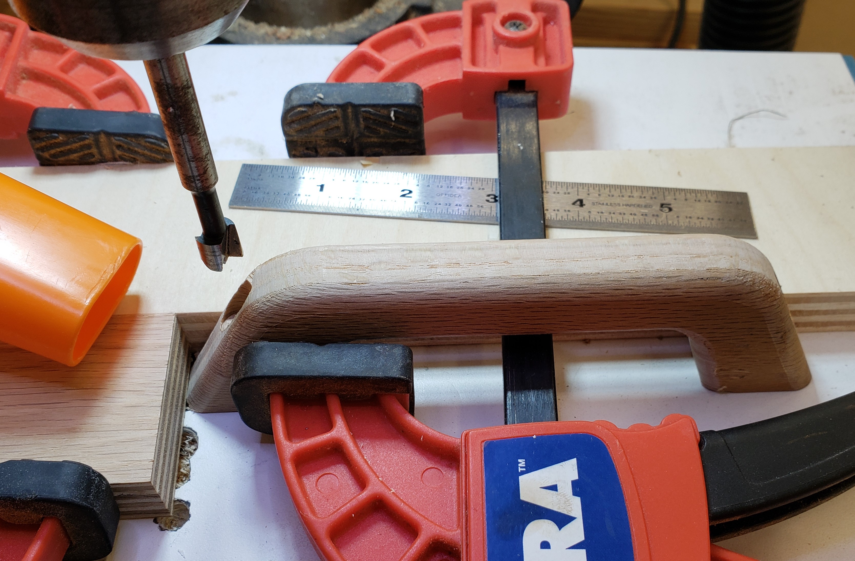
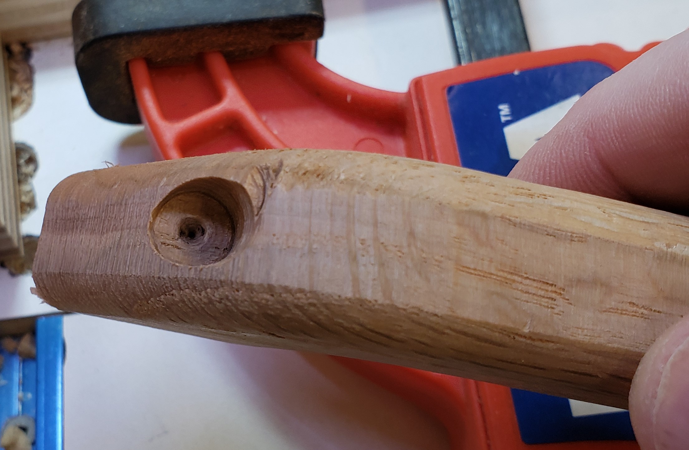
Next the handle blanks got sanded, a round over, and more sanding. I figured I would make their look a little more industrial, and set to counter bore the front for a screw. Lots of stop blocking and clamping was needed for that. This would be stronger than screwing through the back, and easier to install. I like the aesthetics of it too.

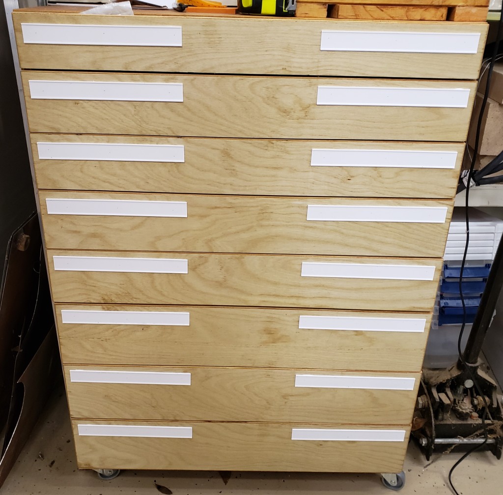
Things were coming together. I needed some labeling, so I printed slots that would accept 1″ label tape without the back removed. It meant I could rearrange tags quickly without peeling anything. A little calking on the back held the holders down. I used a few pin nails to tack them in place while the calking dried. No heads on the pins means they don’t interfere with the labels sliding in from the sides.

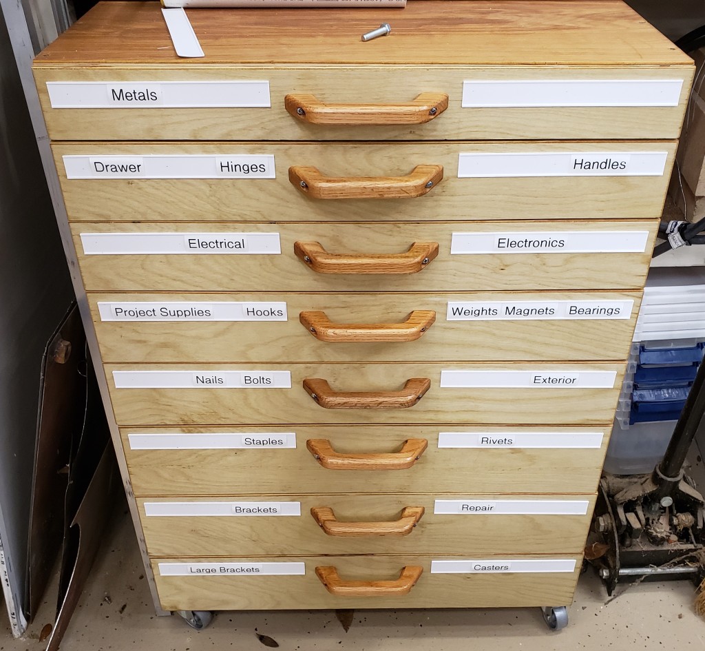
I painted on a little linseed oil on the handles and installed each one down the center. They are comfortable, easy to use, look gorgeous, and finish off a wonderful cabinet. I should make my own handles more often. I feel like my experience and planning payed off. Other than some issues with the handles this job went off without a hitch. I have done a lot of other stuff like it before though, so I shouldn’t be making as many mistakes at this point.

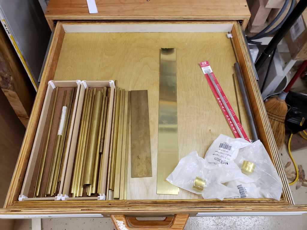
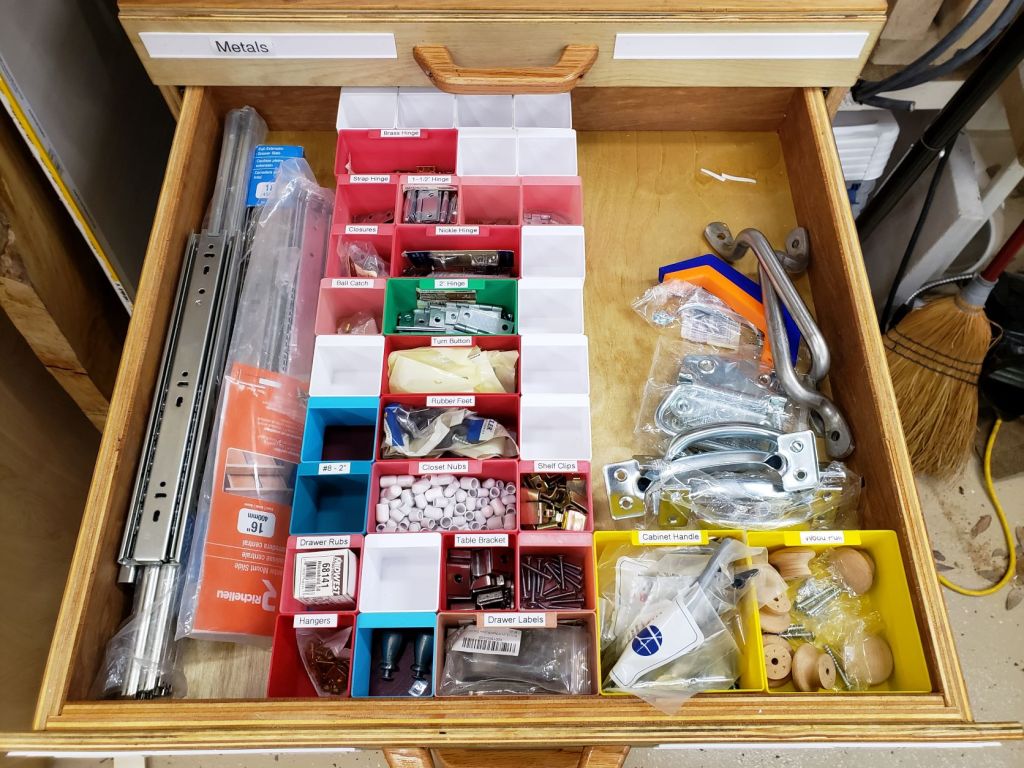
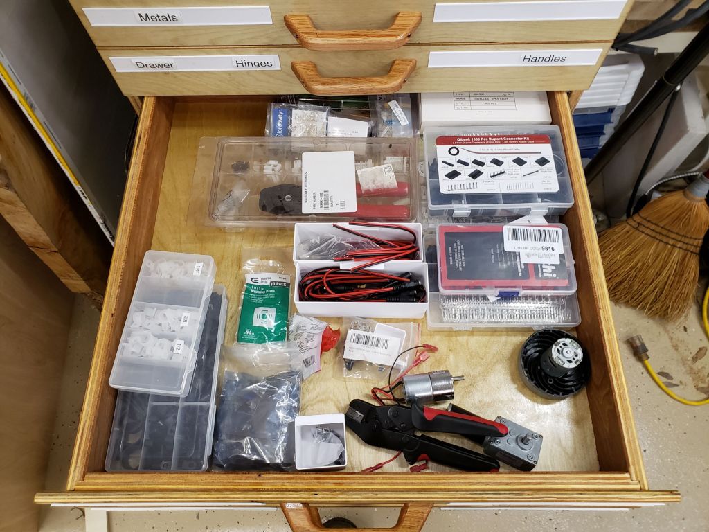
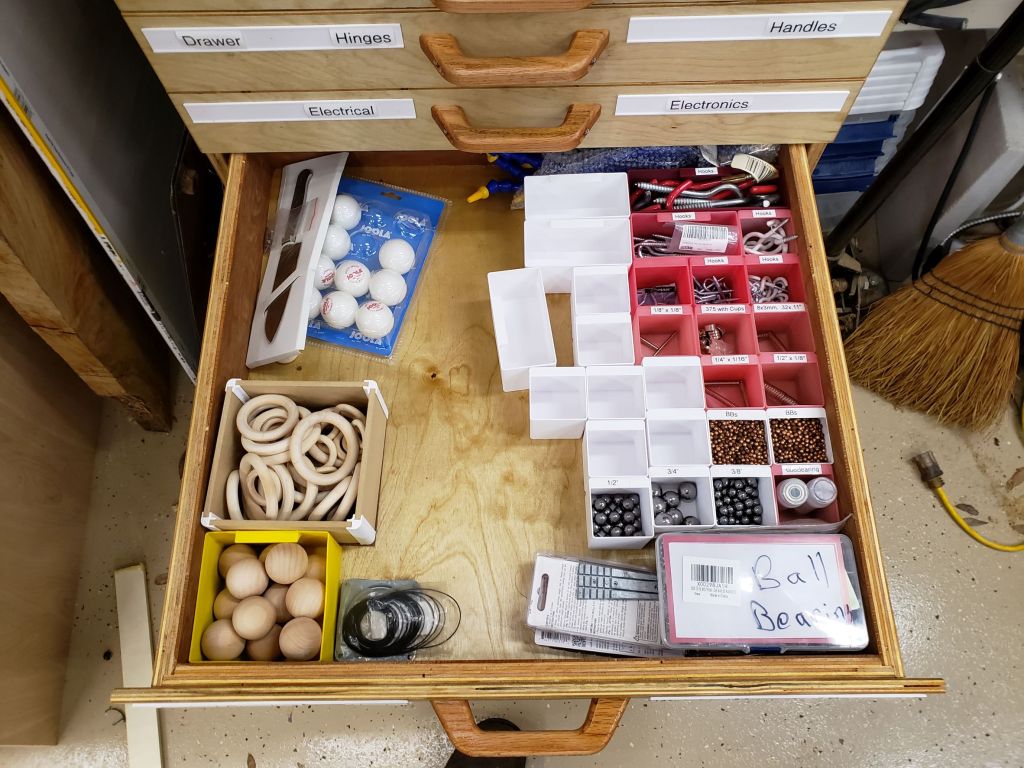
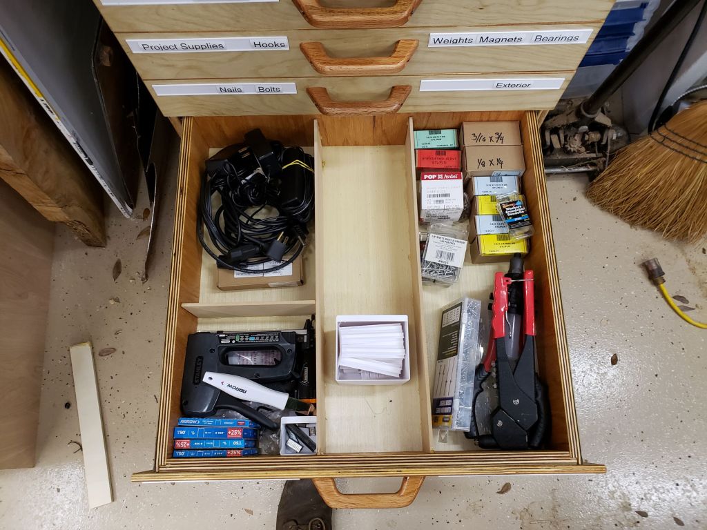
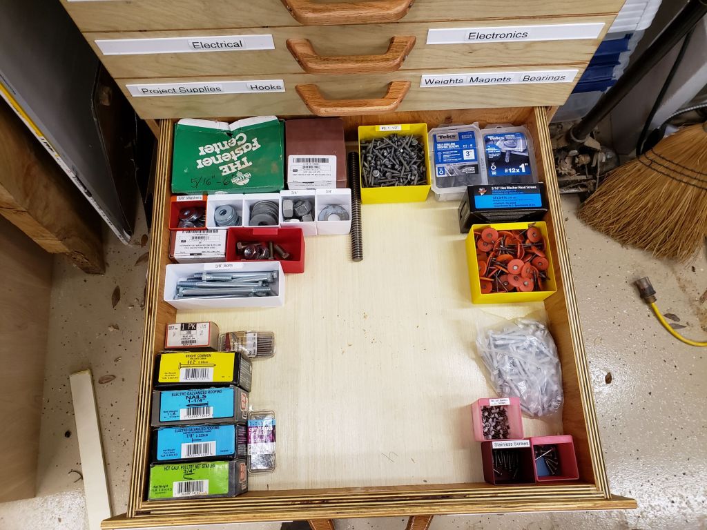
I spent days pulling things out of bins and drawers, organizing, cleaning up and throwing away junk. This isn’t the final configuration, but it is close. The shelves are a lot cleaner and I still have a lot of room left in this guy. It isn’t hoarding if you use labels!

Electric Flamingo

Do Floridians Dream Of Electric Flamingos?

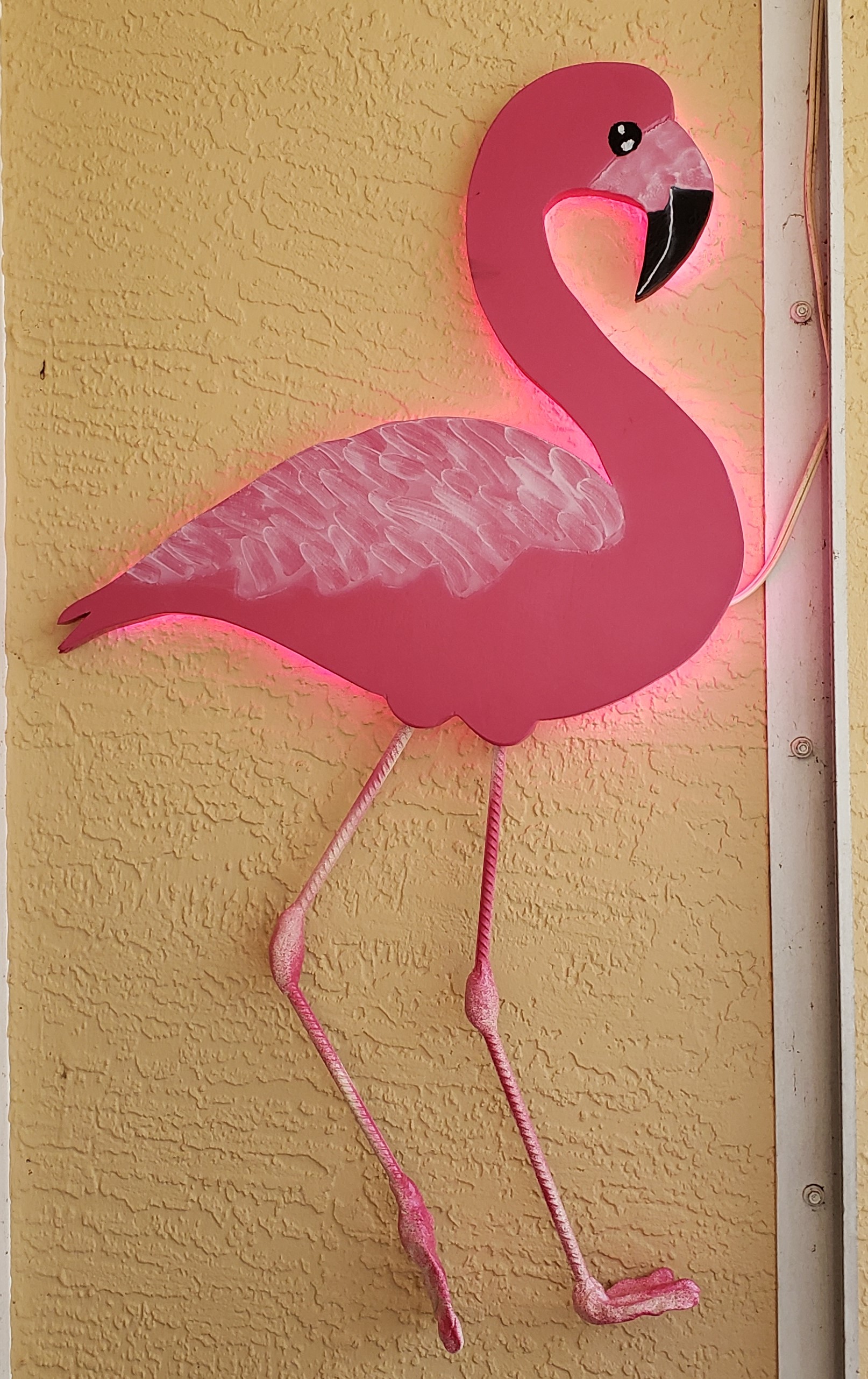
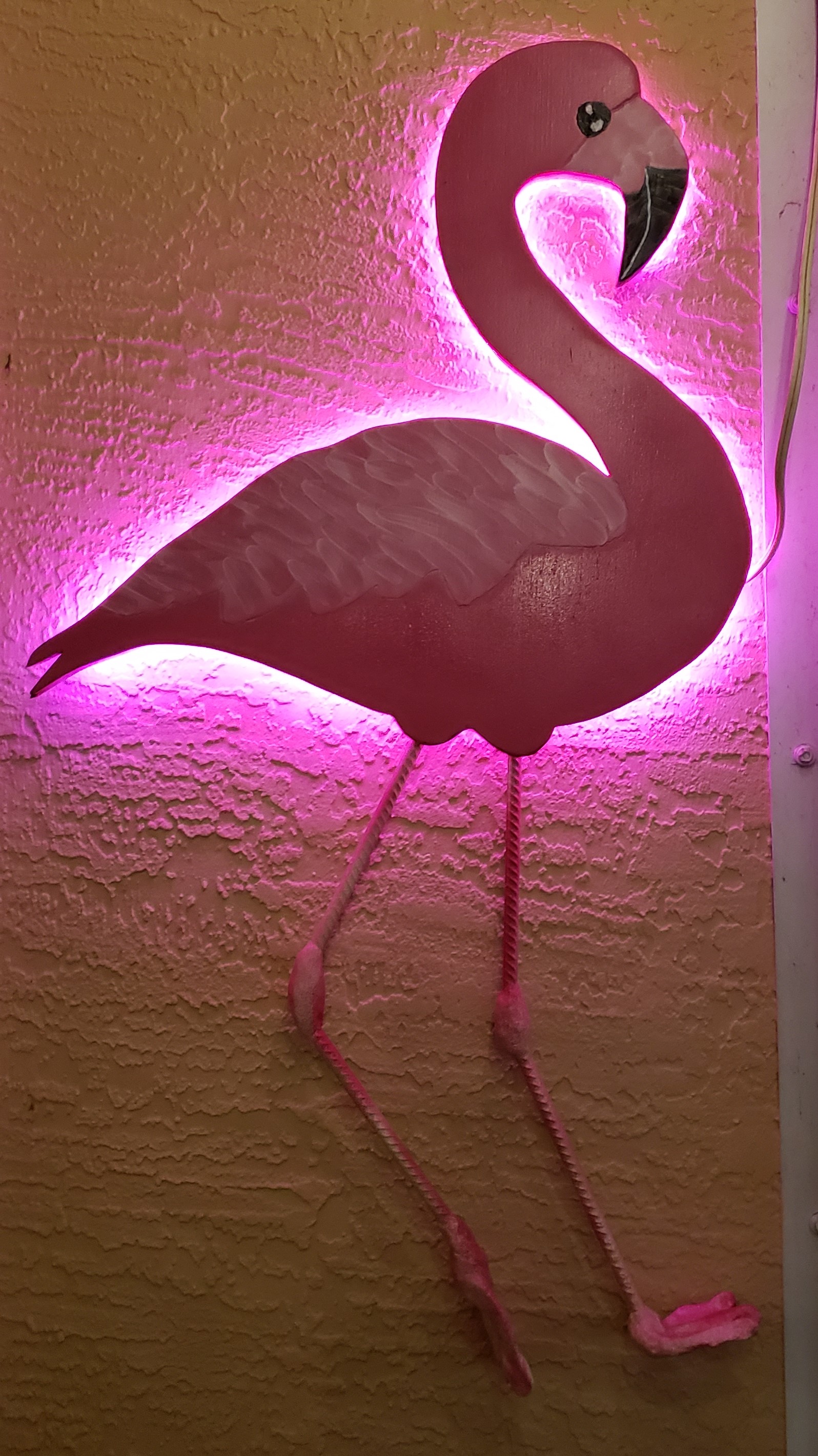
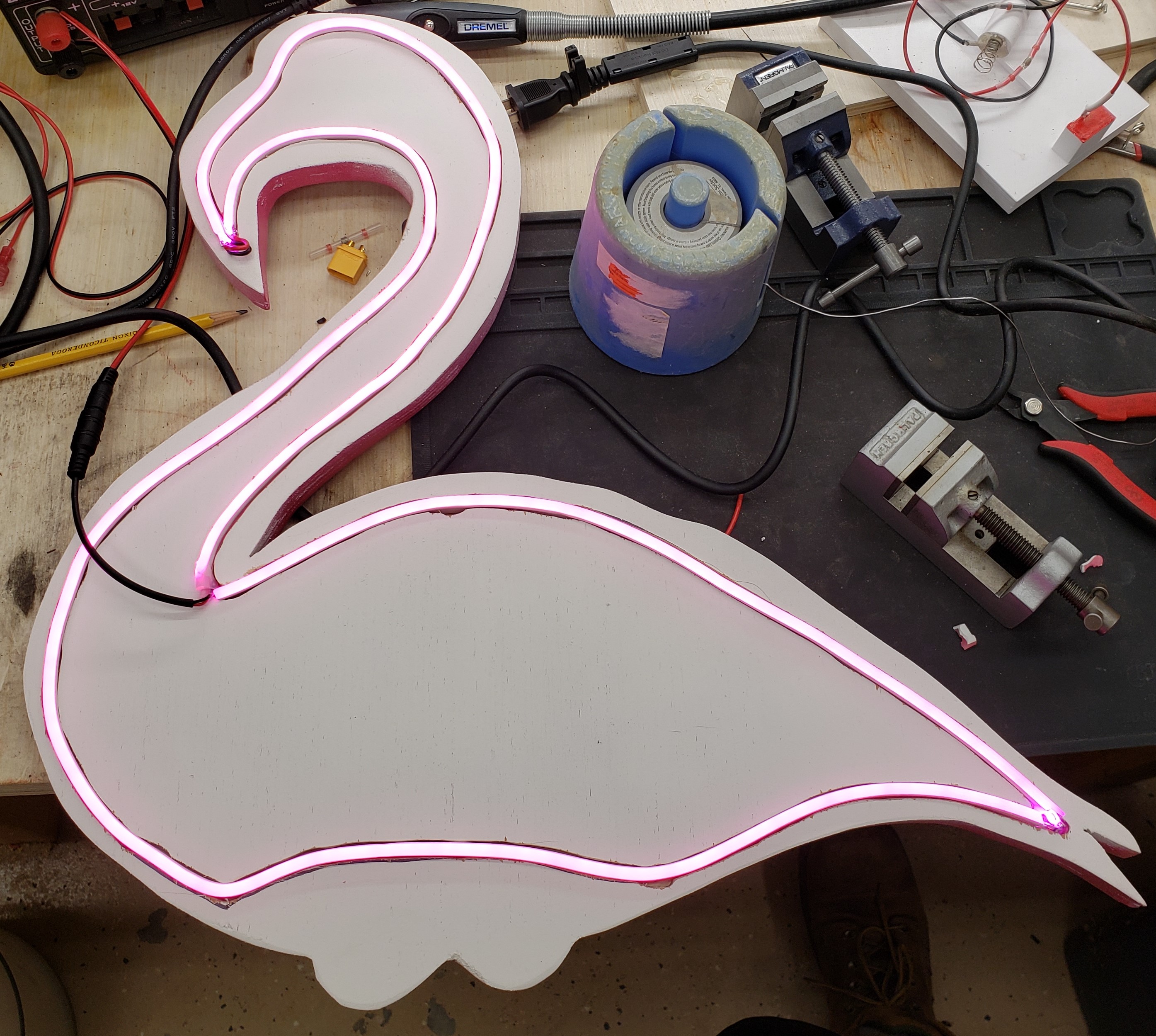
I had this idea for a piece of wall art (using that term loosely) pop into my head. Truth be told it was the legs that first occurred to me. The neon glow didn’t come until later. Here is where we are going. A day and night shot are needed to show its various aspects.

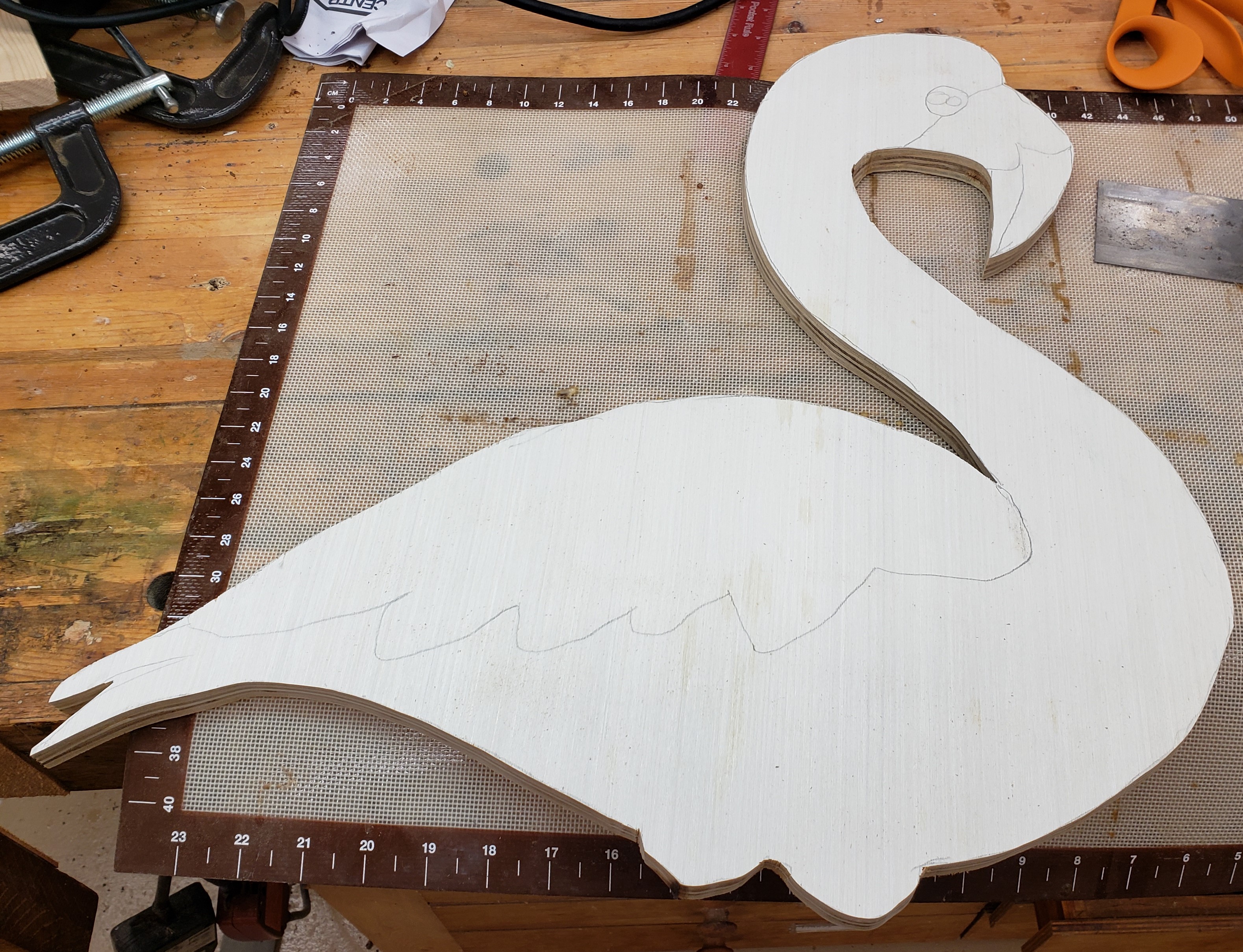
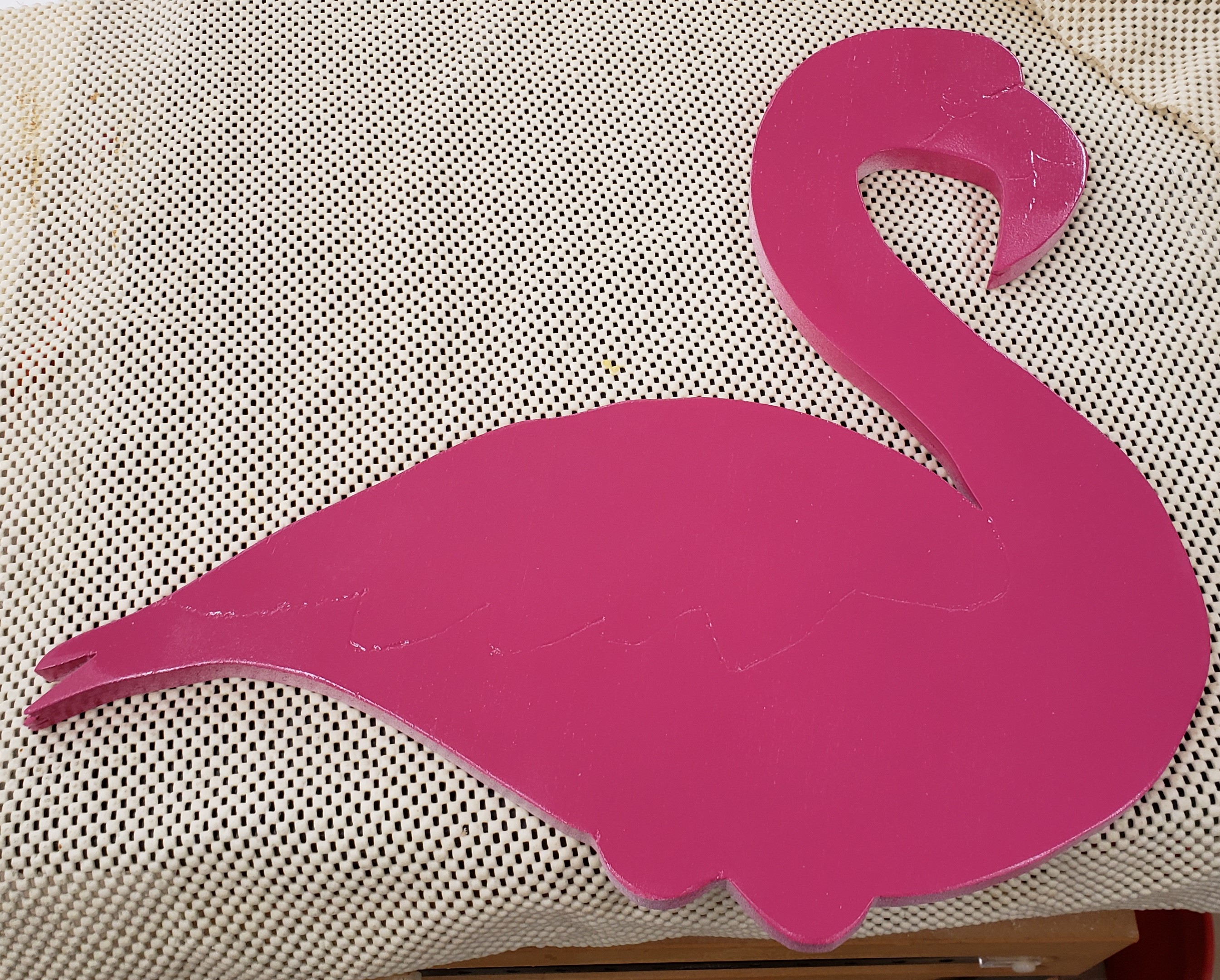
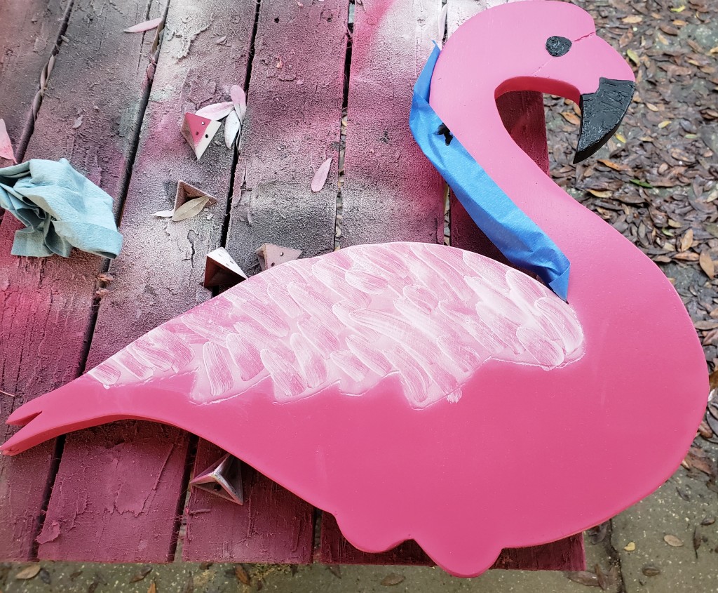
I started by projecting a rough flamingo shape onto a piece of plywood, then tracing it out as I have done in other projects. I used a dremel and a light touch to carve in the lines for other details like the eyes and feather line. I had some hot pink left over from repairing the finish on my lawn flamingos, so I used that as a base coat.

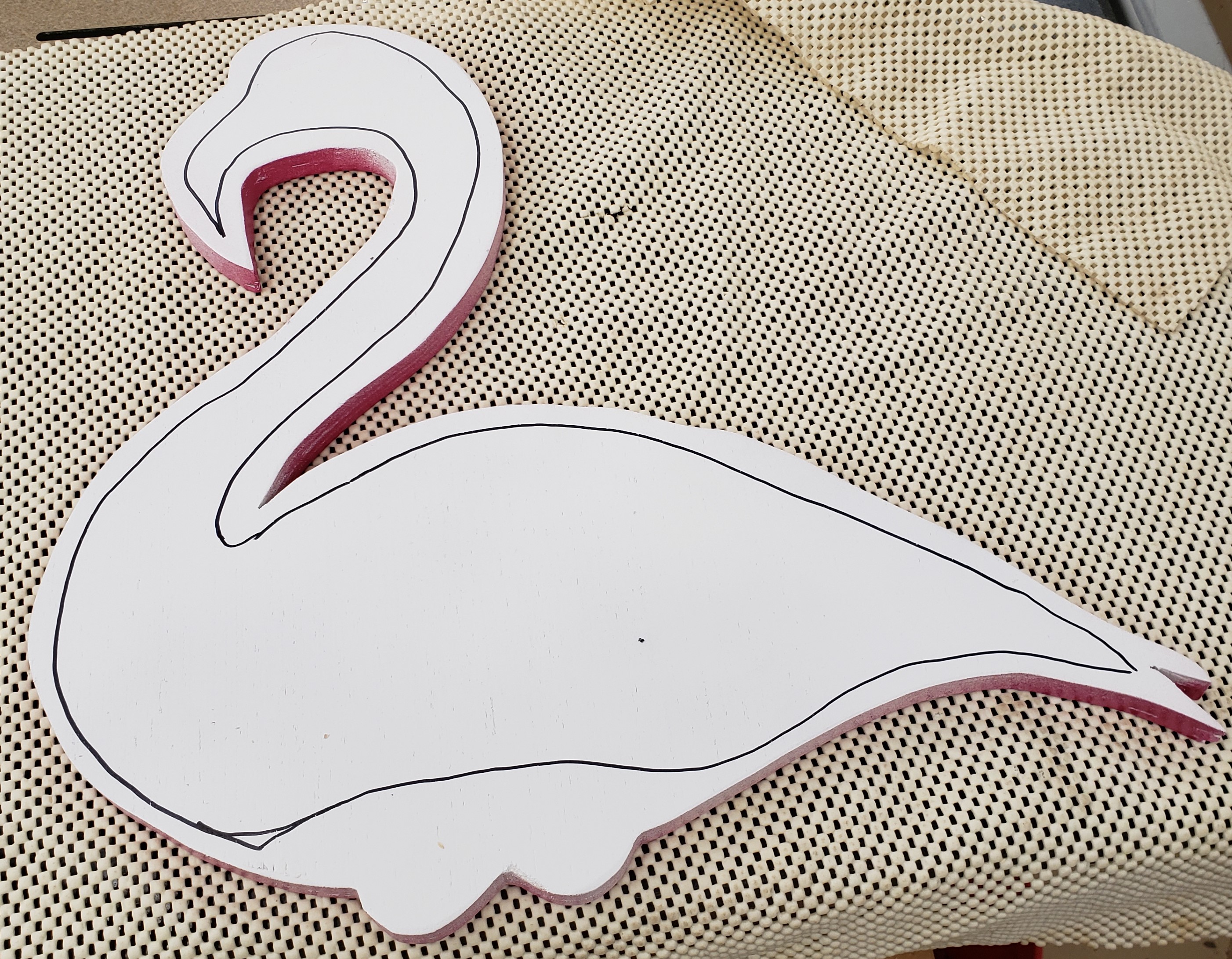
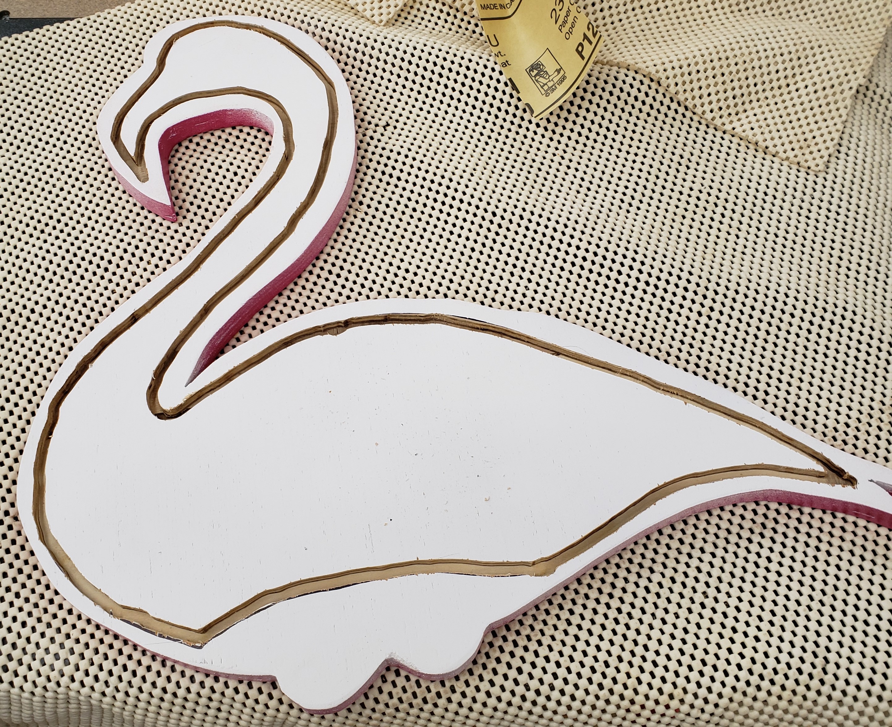
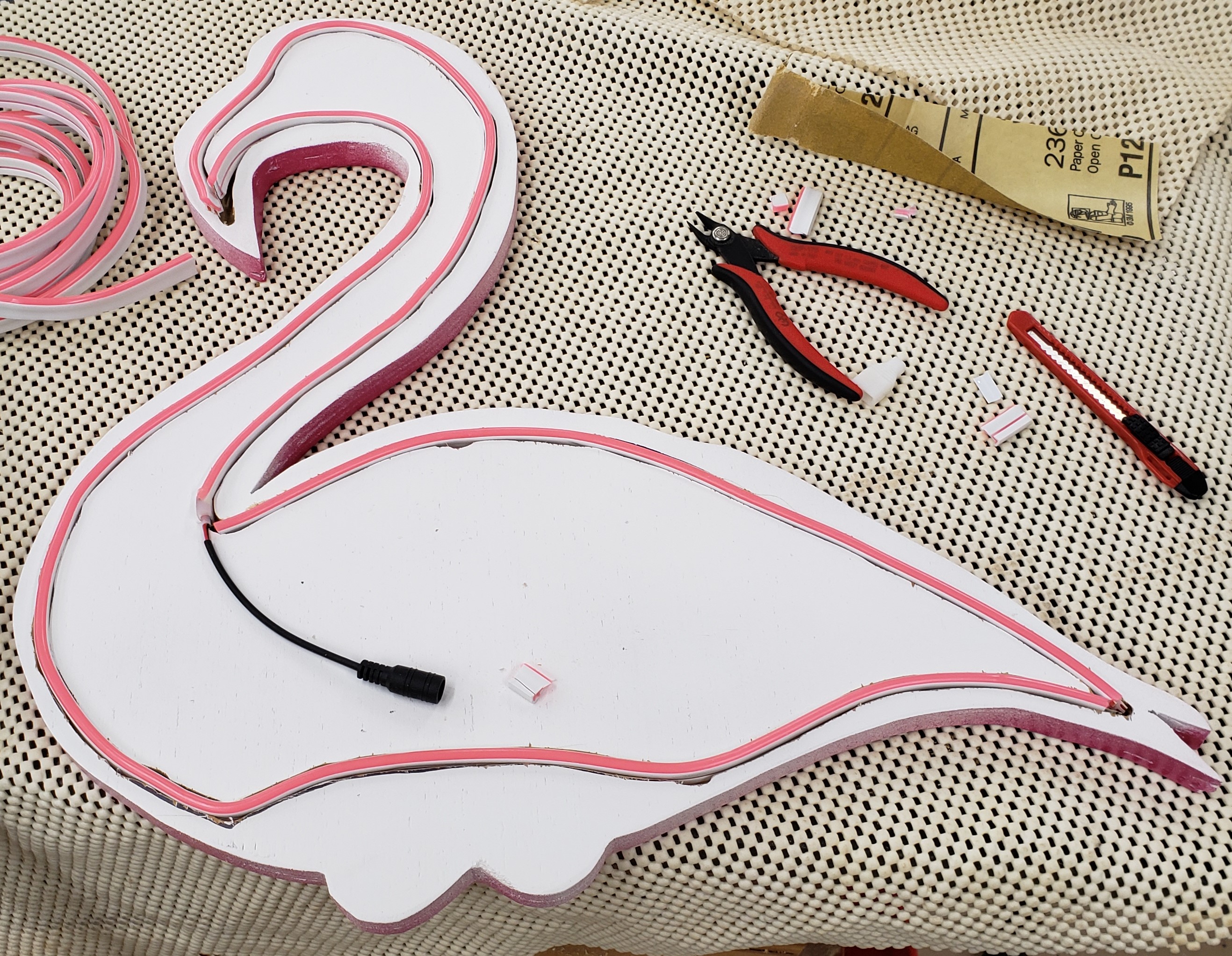
Around this time I saw a video on tested’s website where Norm was using this LED strip that was setup to look like neon sign tubing. It was really gorgeous and I wanted to try it out myself. I found a pink variety that runs on 12v. I free handed an offset from the outside edge of the flamingo and tried to follow it with a 1/4″ router bit. That gave me a good groove to seat the LED strip in. You have to cut at specific locations and solder together the ends to make it a continuous strip.

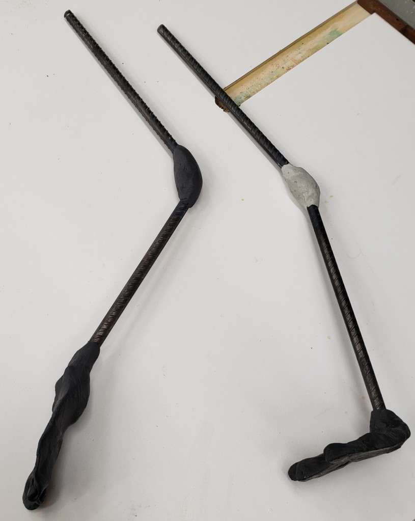
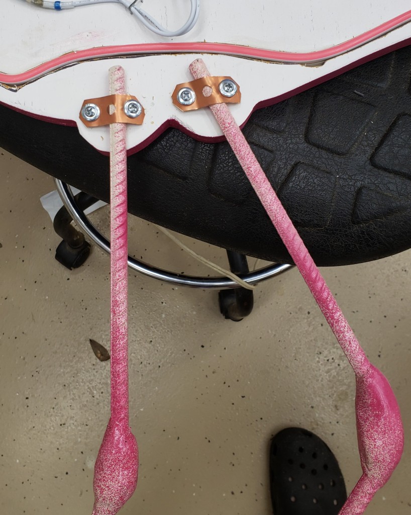
The project started when I had this vision of making flamingo legs using rebar and epoxy putty. Not sure why that came to me, but it did. Sure enough, bending rebar after a bit of torch work and then using epoxy putty to make knees and feet is a good way to make flamingo legs. I am no sculptor, but they came out good enough from a distance. I used a bone color as a base, then did a splotchy overspray of pink to add texture.

To add the rest of the feather color I used my air brush. I was going to try to airbrush a feather texture, but it didn’t really turn out like I wanted. In trying to wipe some of it off, I made a thumb smudge. It looked pretty good. I started from the back and worked my way forward doing air brush areas with finger smudges to make it look like feathers. The lighter area around the beak was airbrushed, but the beak and eyes were done with a normal brush.

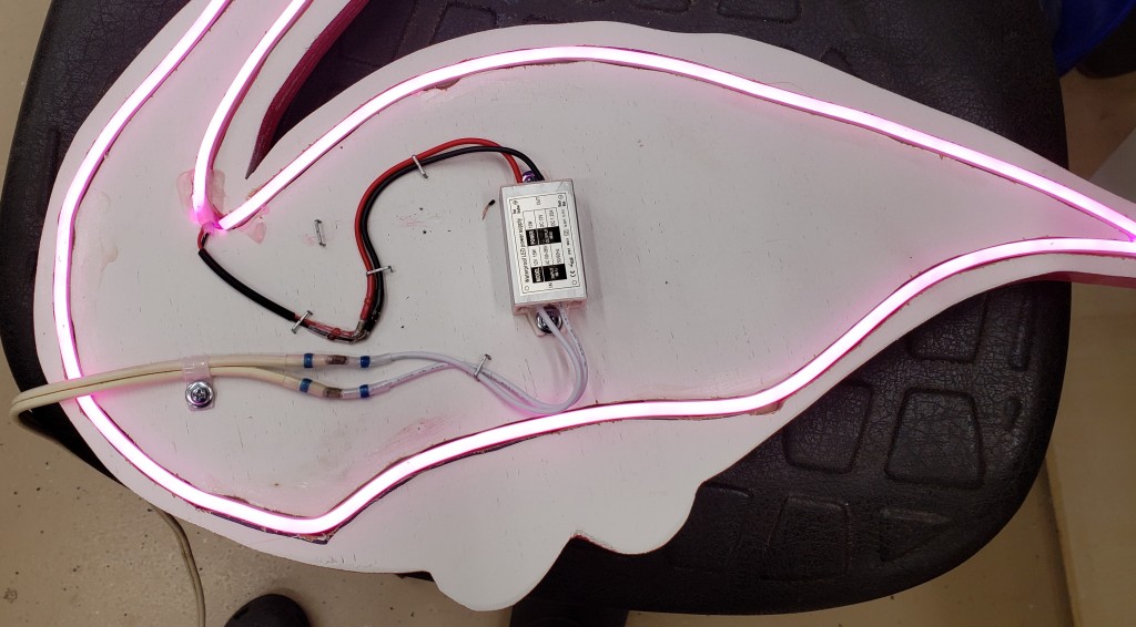
I found an outdoor rated power supply to run the LED strips and soldered it to an extension cord to minimize the space and wiring needed for this. There is a hard wired power cord for my flamingo now. I used metal pipe strap to attach the legs. Overall, it took a few twists and turns, but looks awesome on my porch. I need to do a little better job hiding the power cord against that hurricane track, but otherwise it is great.

Cedar Porch Side Table

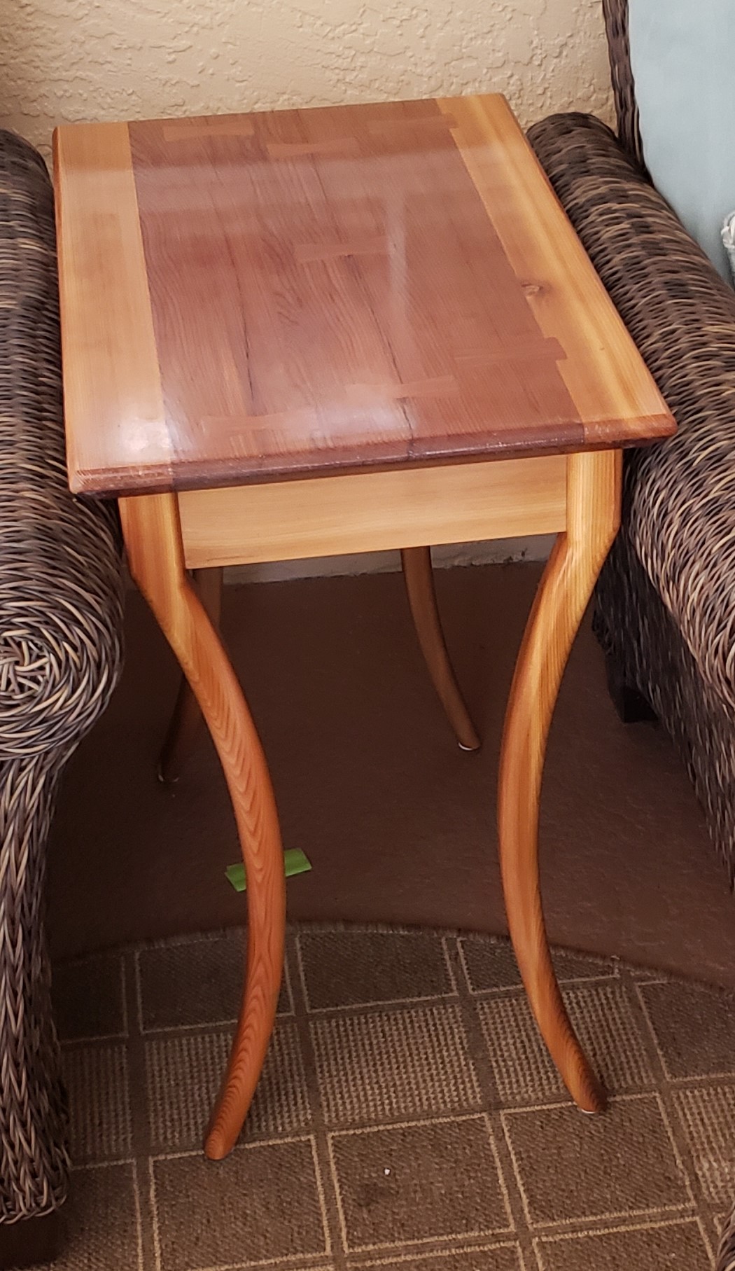
When we first moved in to our house we bought some fancy wicker chairs for the back porch. They are lovely, but we weren’t wild about their side table options. “I’ll just build something!” I said. 3 years later we were still using a junky wooden folding table the previous owners had left. To be fair, it was at the right height, but was rather small.

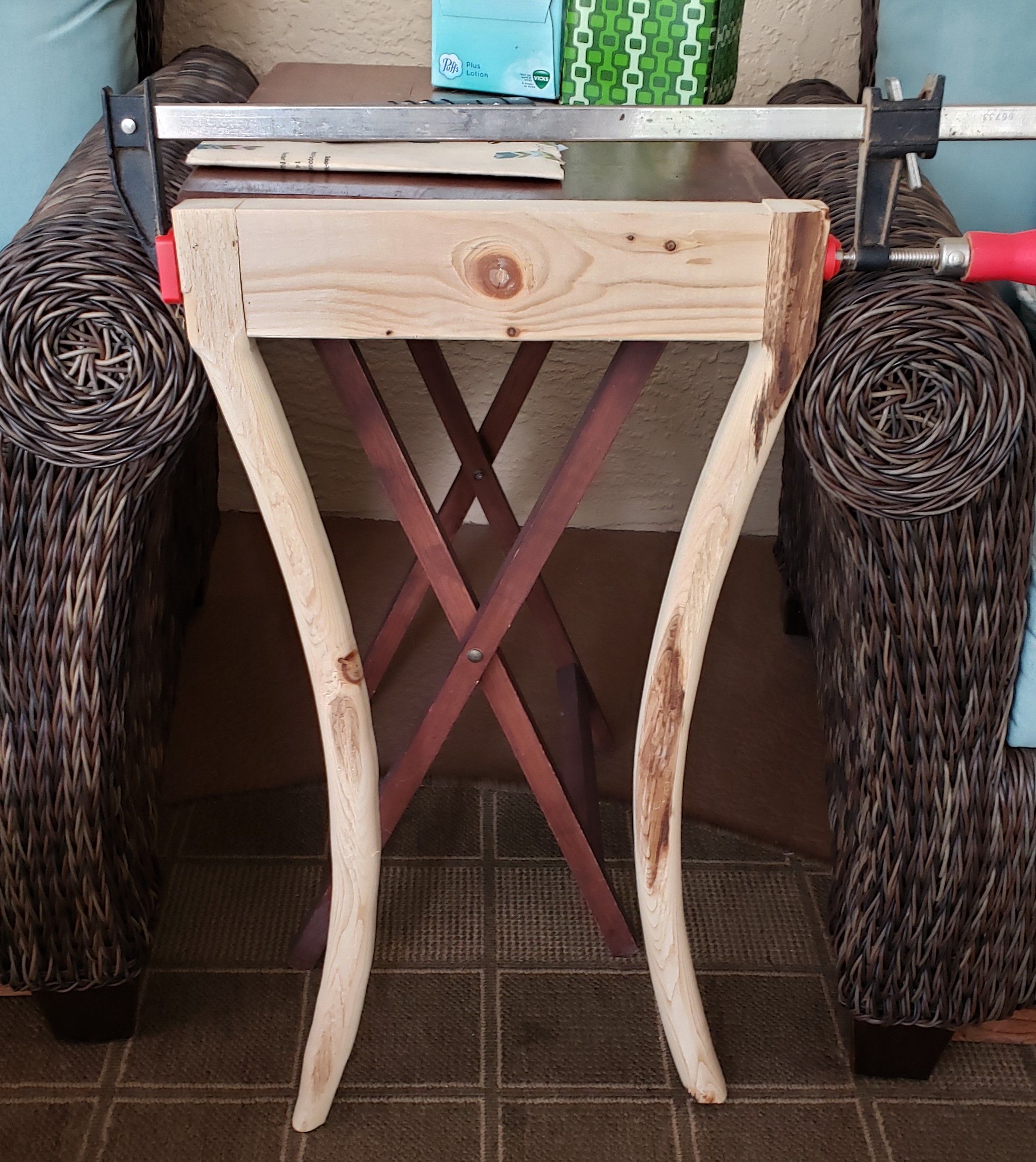
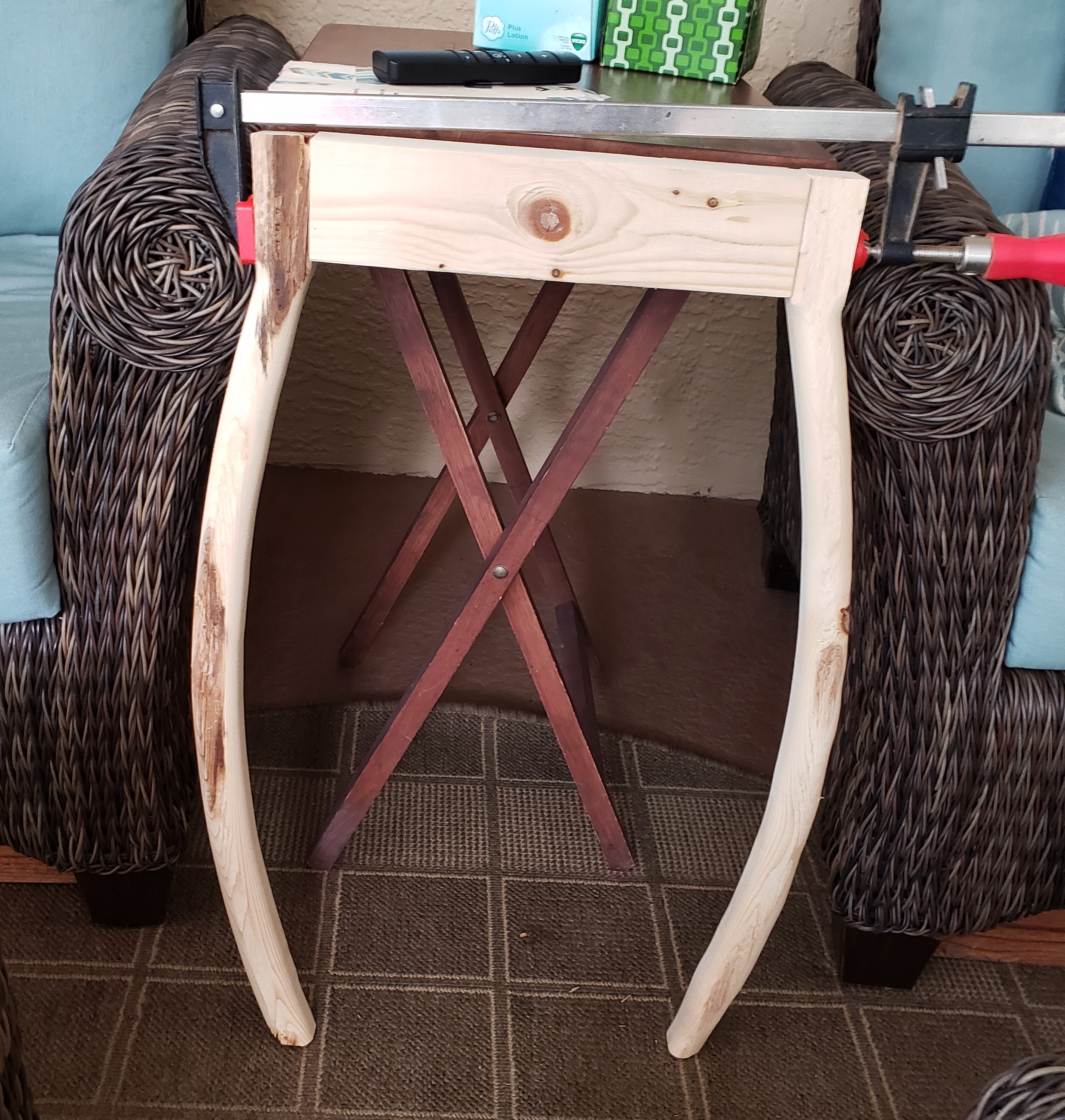
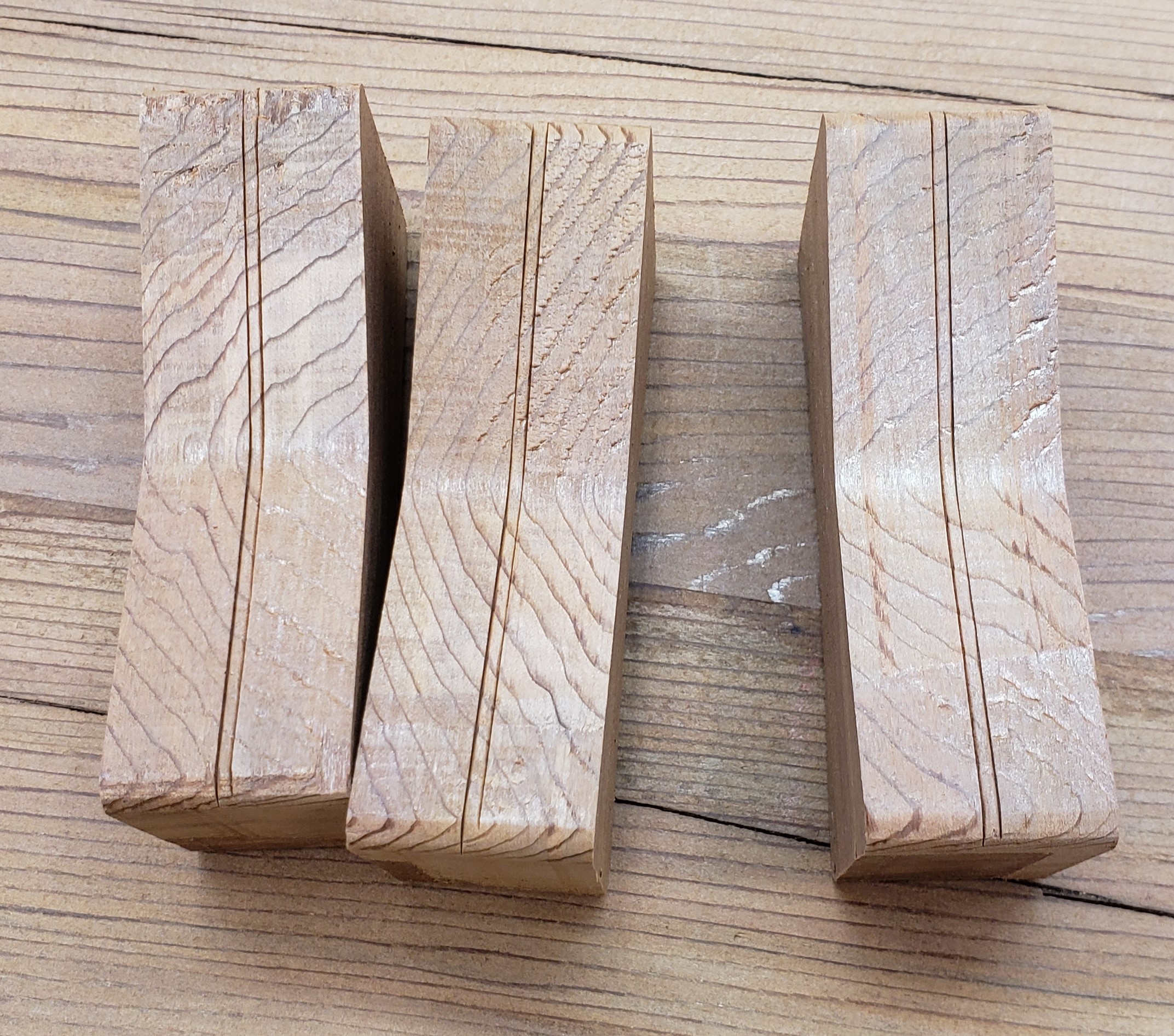
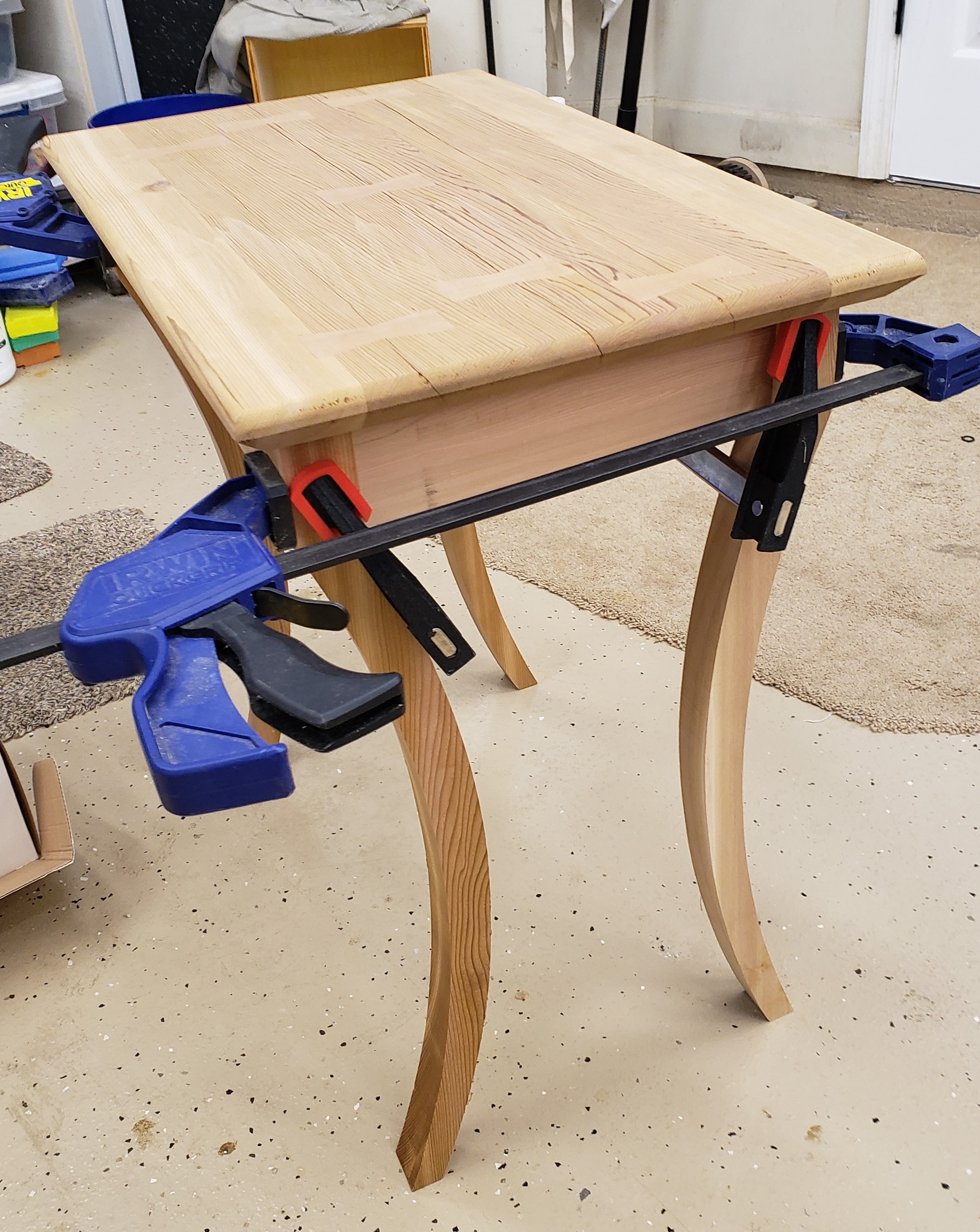
I kept having this idea of using cedar 2x4s to make the legs, and cutting a bow in the legs to make them match the chairs. I used some junky pine to cut two rough legs and mock up an inward and outward bow. The inward concave version kind of matches how the chairs are shaped and is how I will proceed.

I picked cedar because it is available to my local hardware store, is reasonably priced and is supposed to be good for outdoor applications. I did not realize how soft it is and probably won’t build anything else nice with it again. It dents and tears out really easily.


Table Top

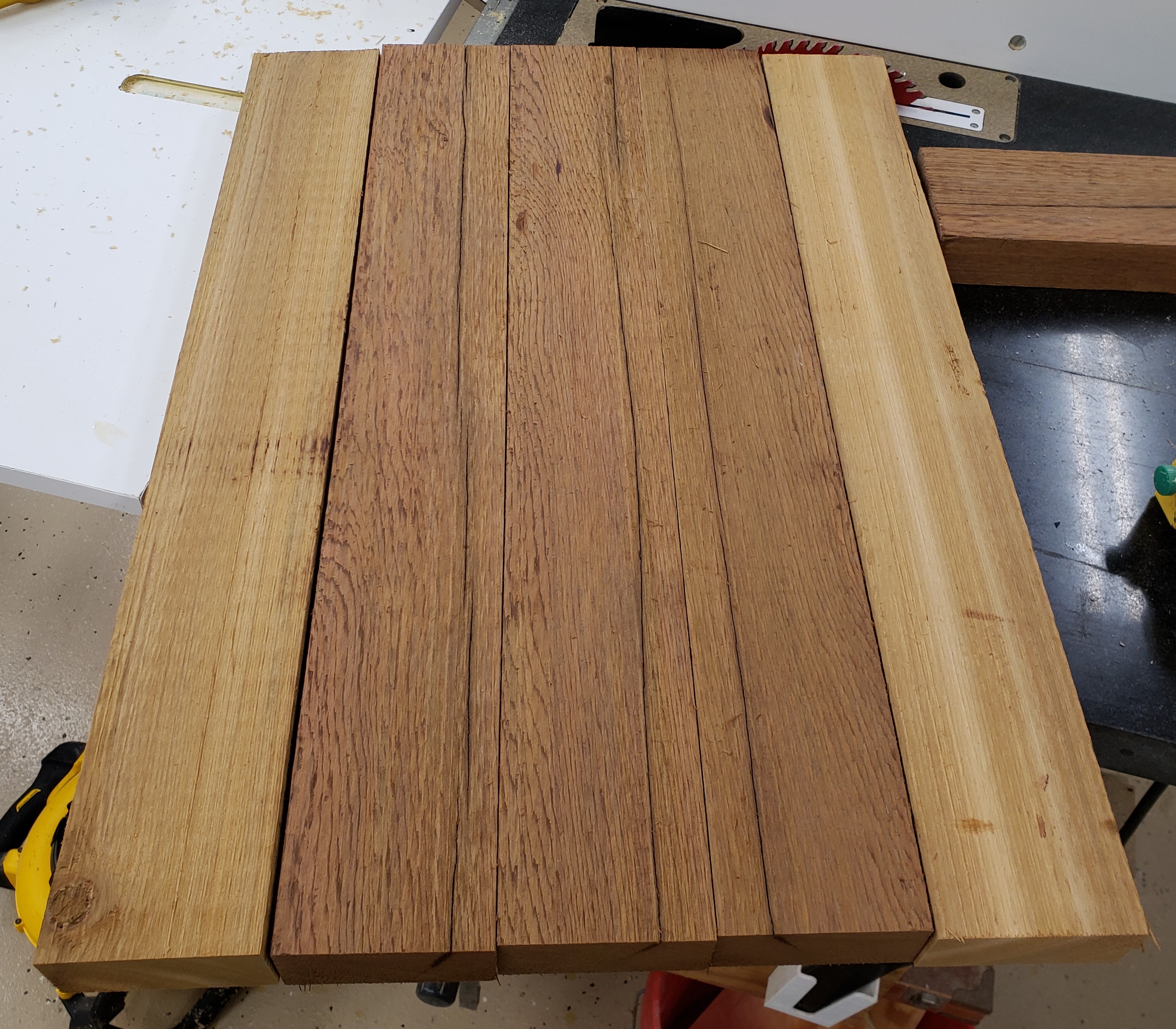
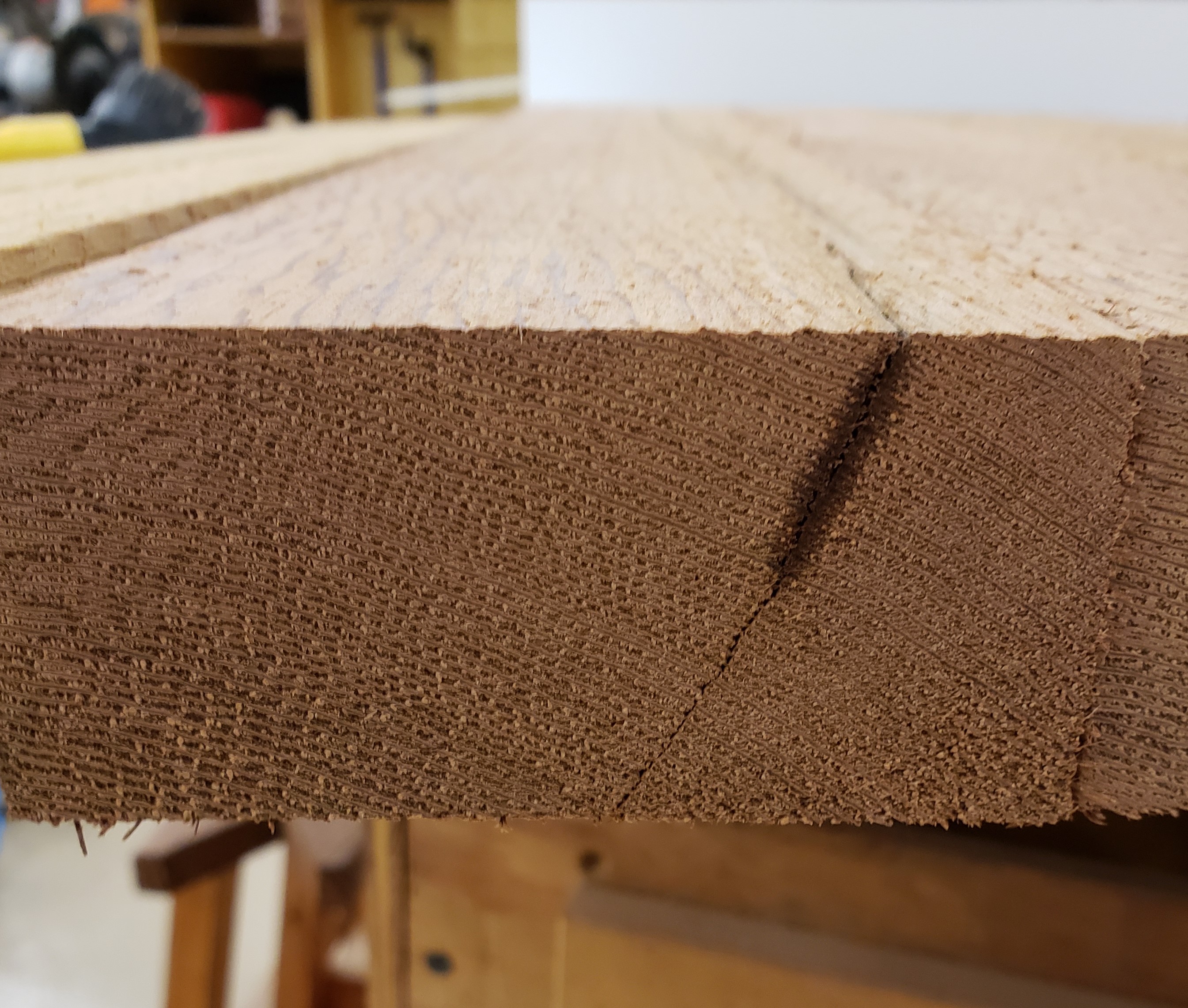
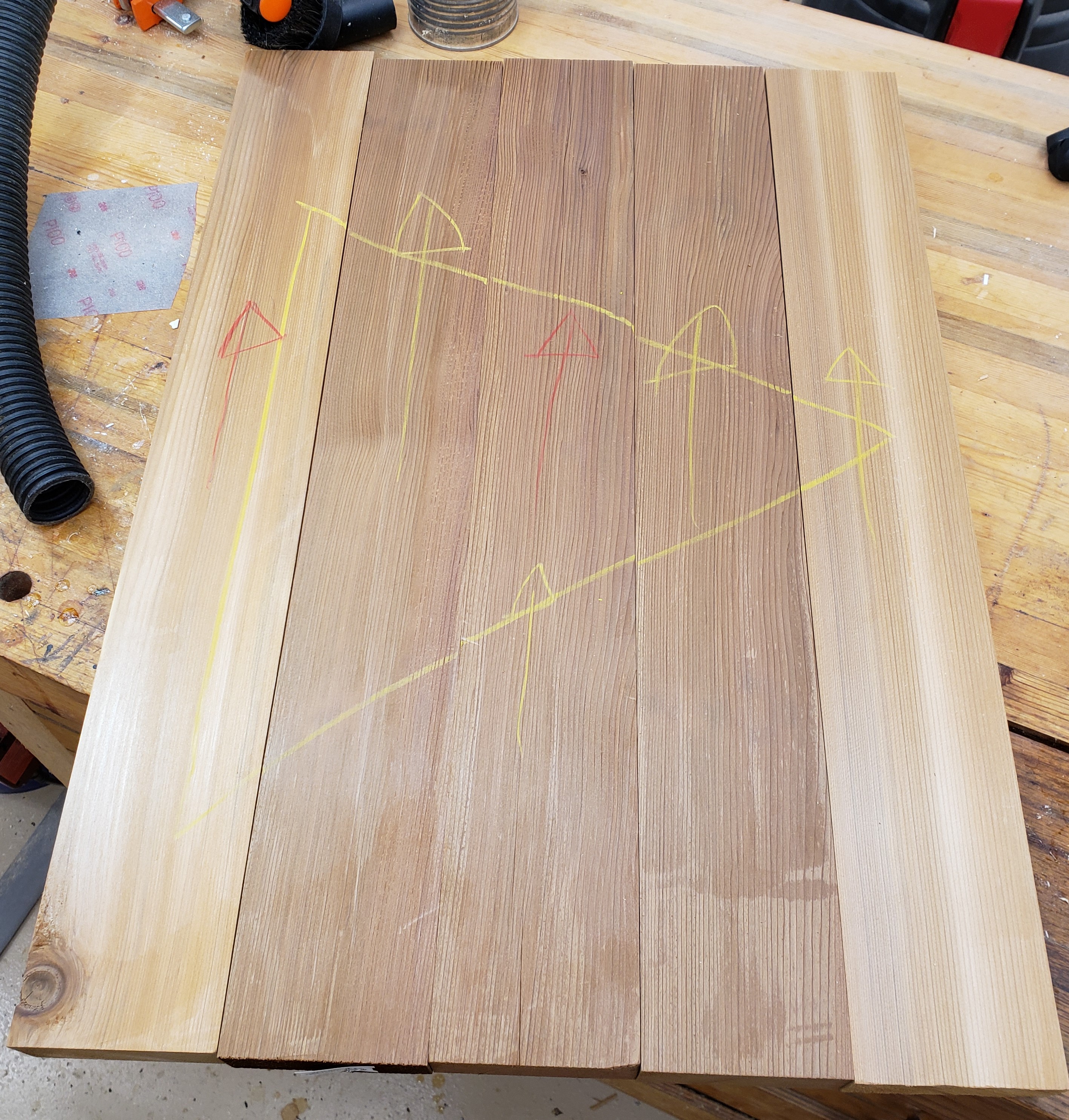
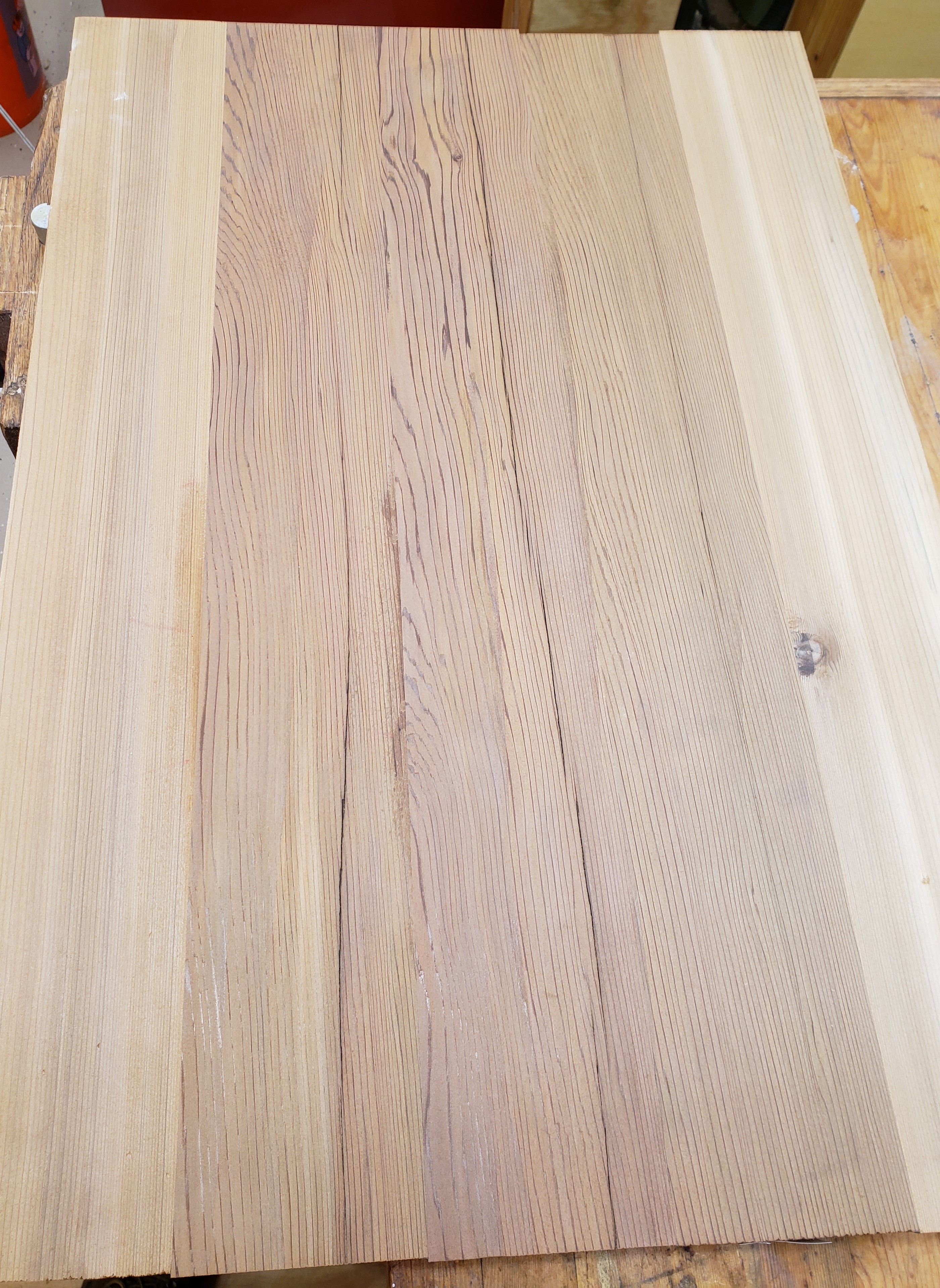
I knew the size I wanted the table top to be so I started there and will build the legs and aprons to follow. I mixed some darker and lighter wood to create a little contrast on the top. These were the straightest cleanest grained pieces I could find. They had a bit of a split that looked ok to start with, but got more apparent as I milled.

I hadn’t used my hand tools in a while but used this chance to flatten all the boards and check grain orientation. After glue up I picked up the top and figured out how bad those splits were. The whole top would flex around those splits like a taco. These will have to get fixed.

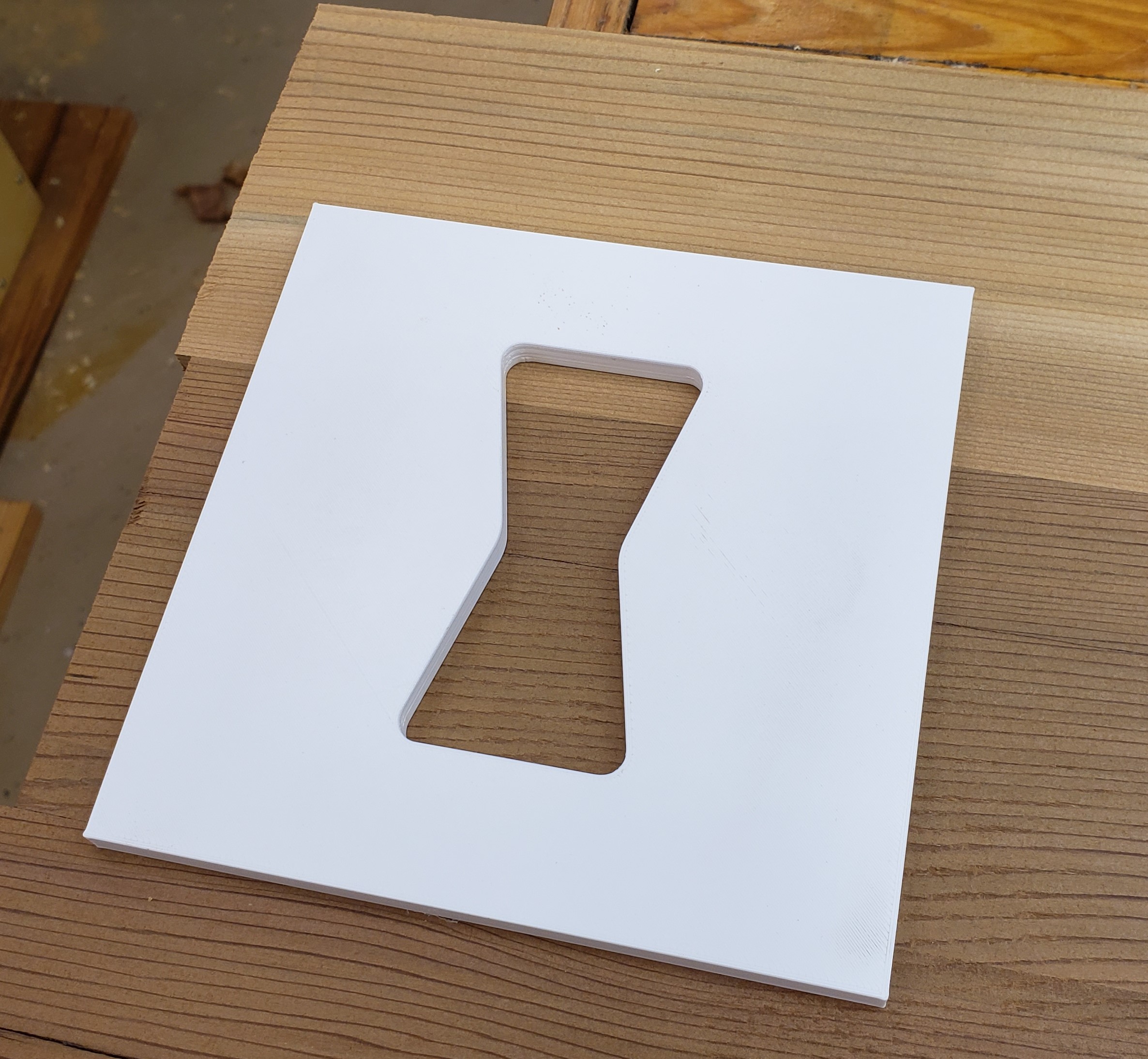
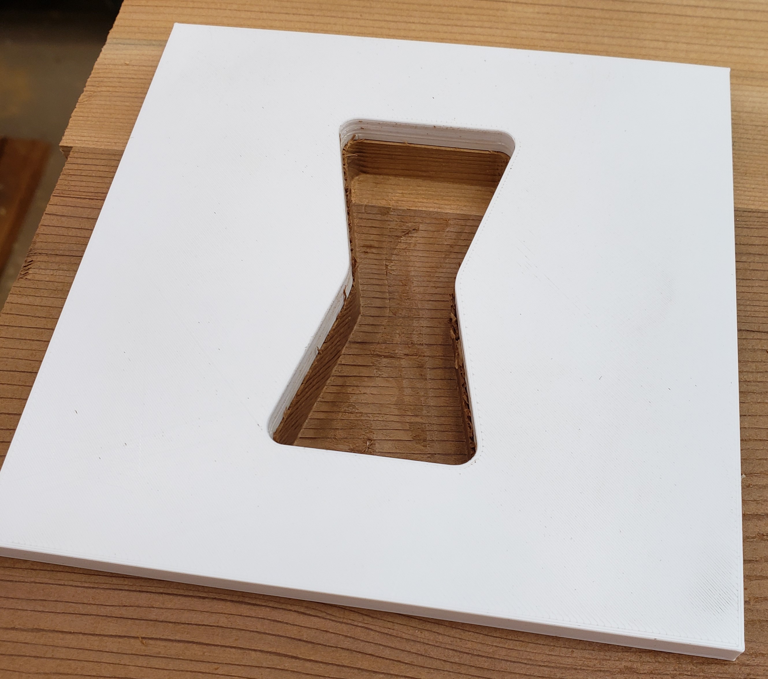
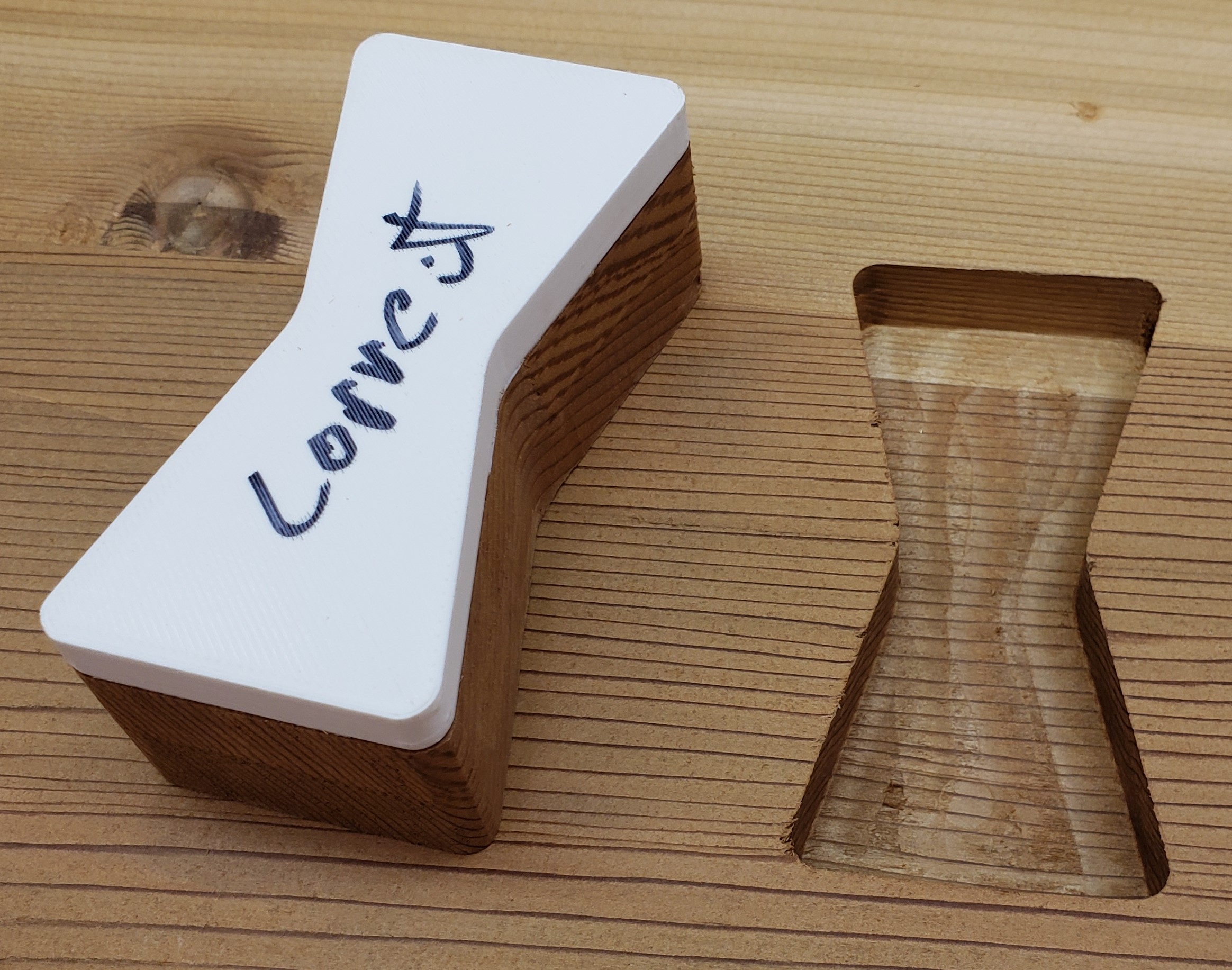
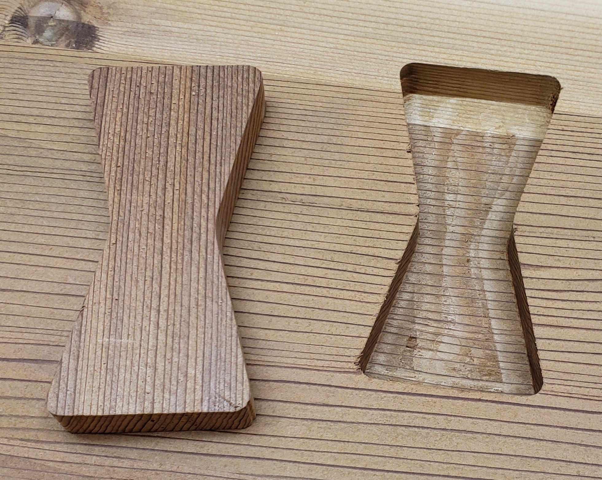
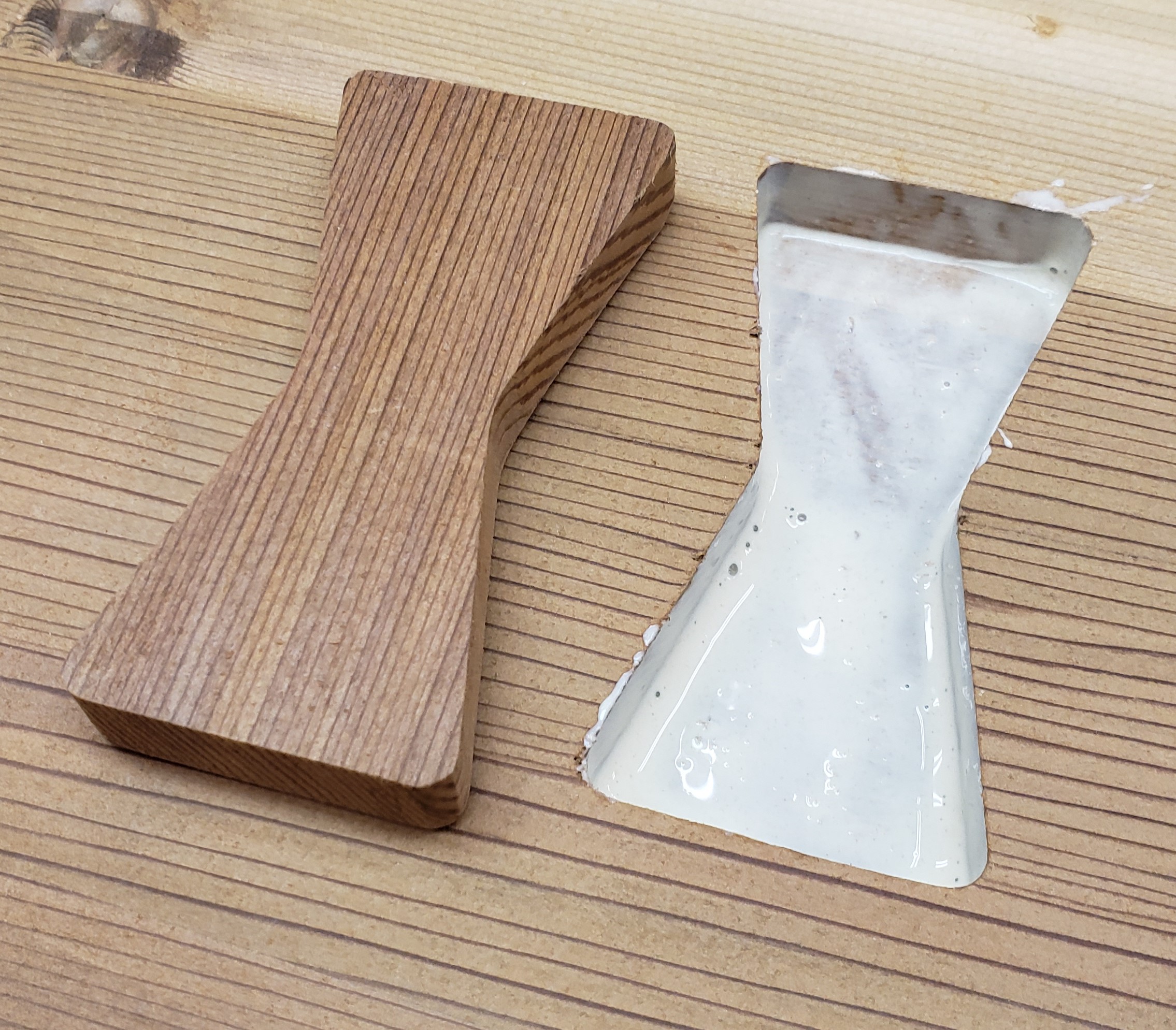
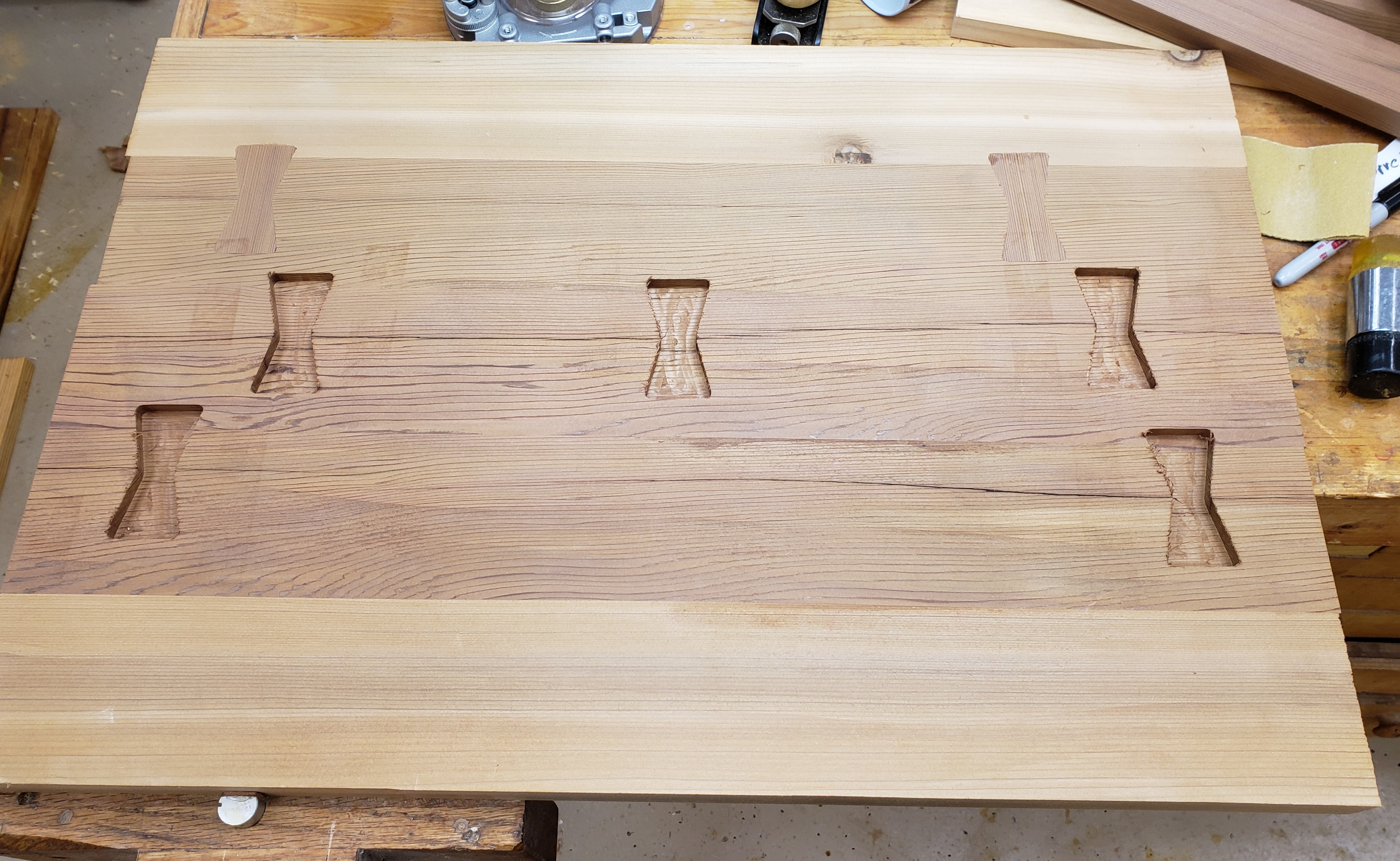
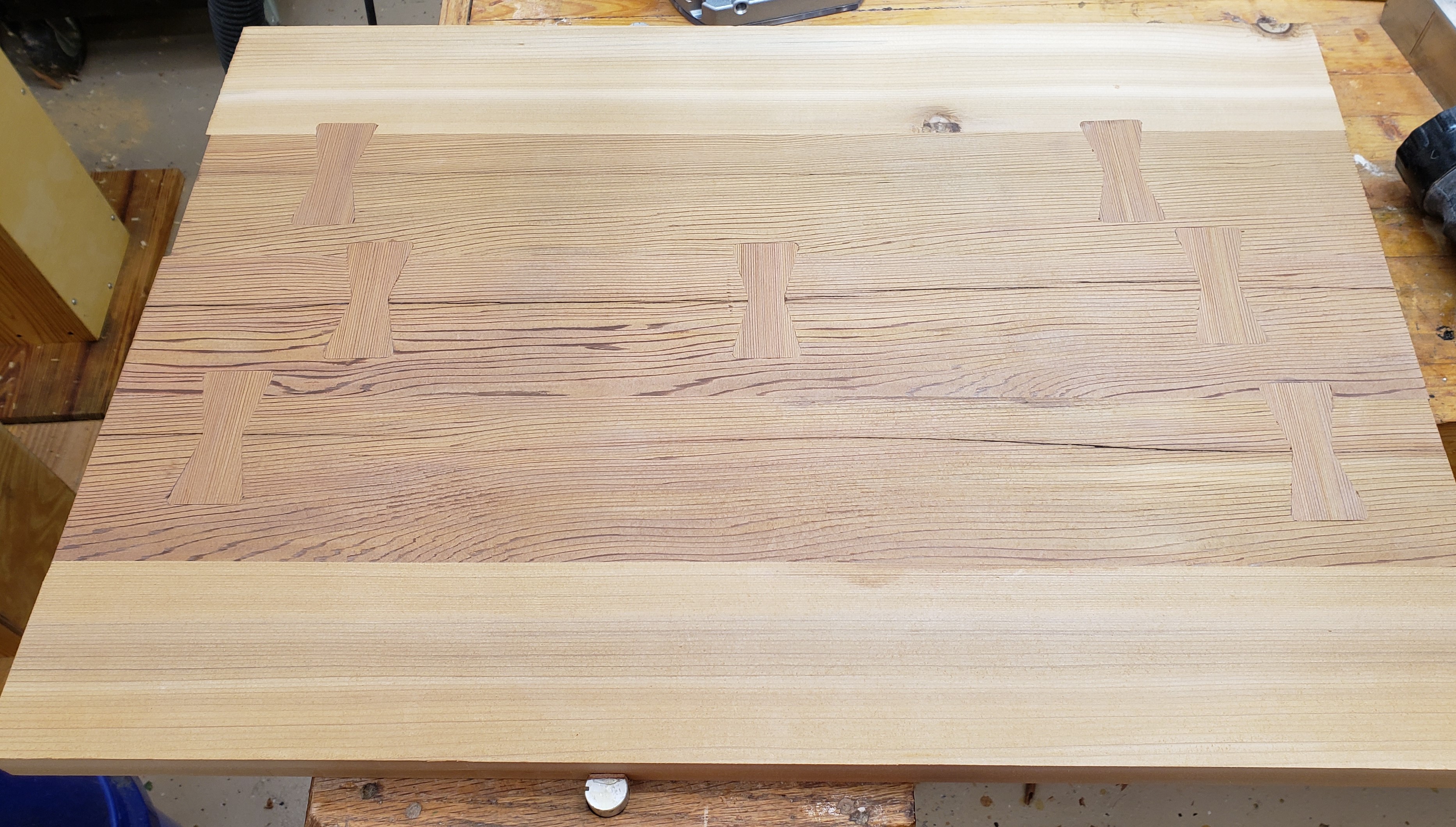
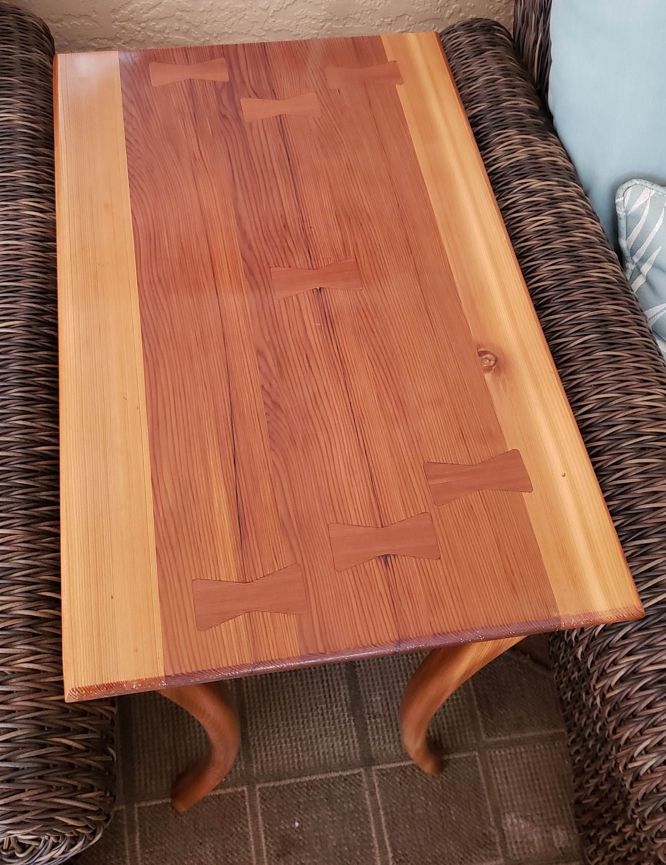
My quick little side table is becoming less quick. I have never done butterfly keys, but why not start now?! It took a few iterations but I made a key shape that my pattern bit would replicate and matched the corner radius a 1/4″ router bit would produce.

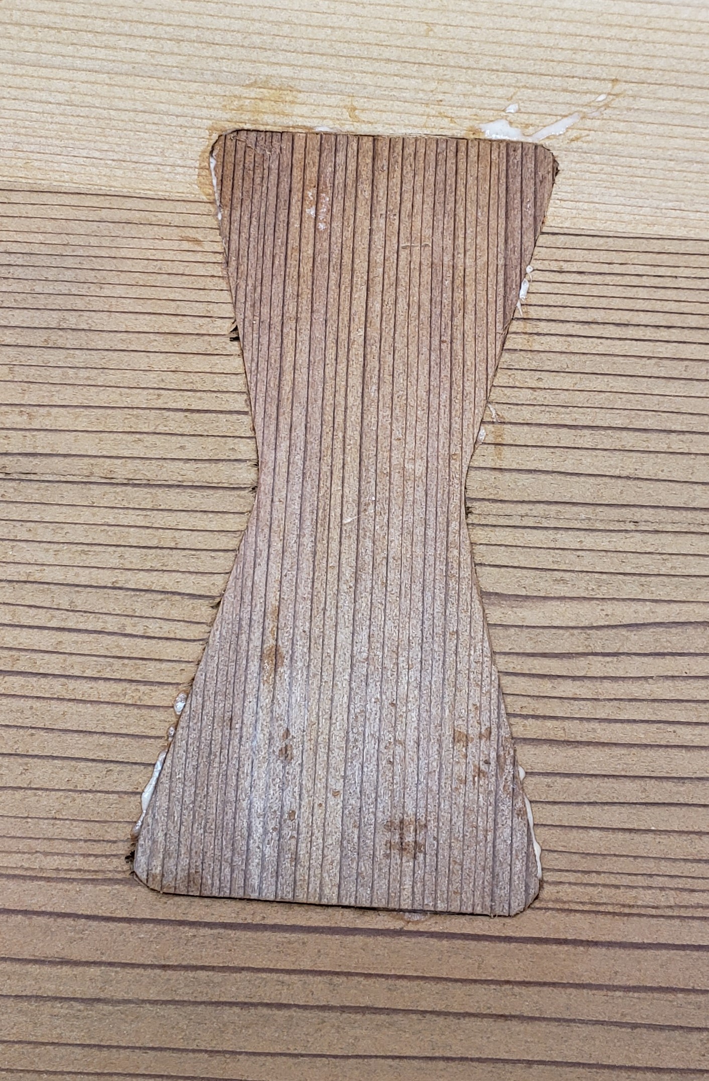
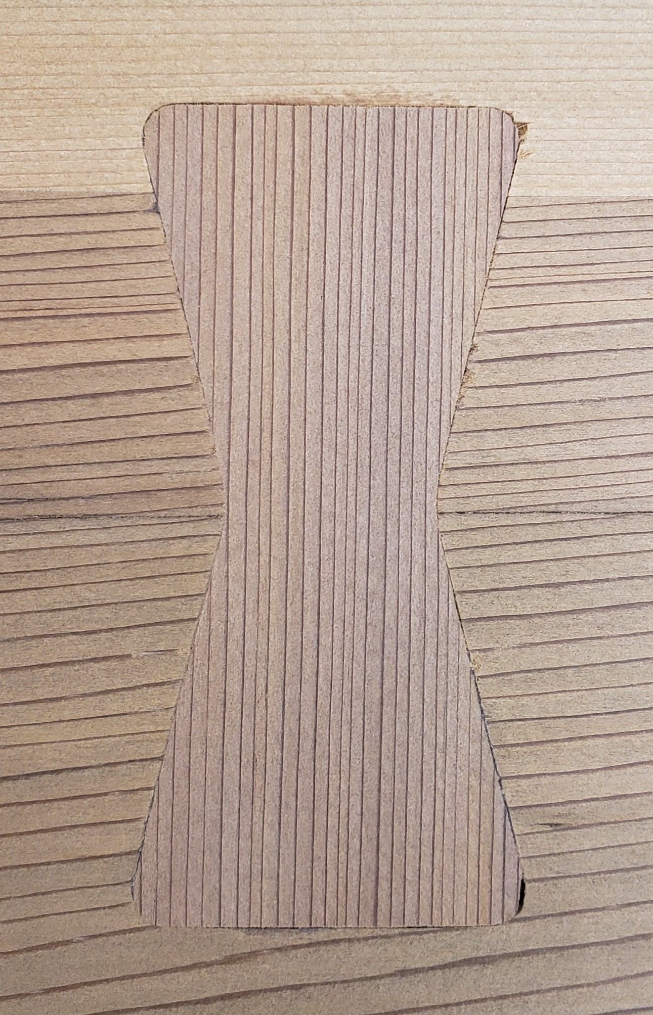
First you use double sticky tape to place the template. Plunge route the socket that will accept a key. Tape a template to the top of a key blank and pattern route the key. I made them tall enough to resaw and get two keys per pattern. I cleaned up the socket area, glued in the key and then planed the area flush.

The other side of the top looks much cleaner and was originally what I was going to show. After the keys turned out so well I showed it to my wife and she thought it looked better that way. Not sure if it qualifies as Wabi-Sabi or not, but it feels like it to me. With all the keys installed the table top feels really solid and doesn’t flex anymore. I trimmed up the edges and put a roundover and chamfer all the way around.


Legs

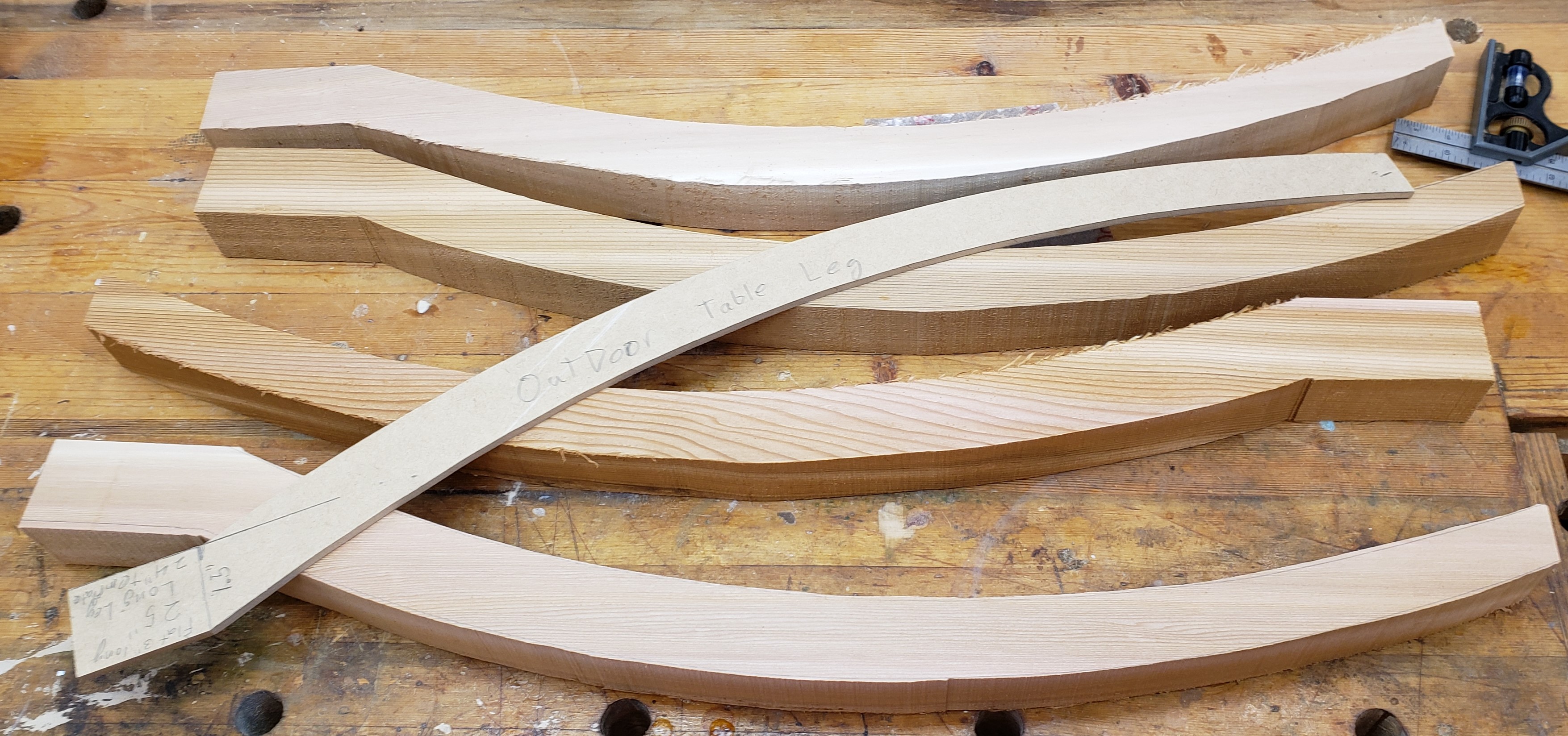
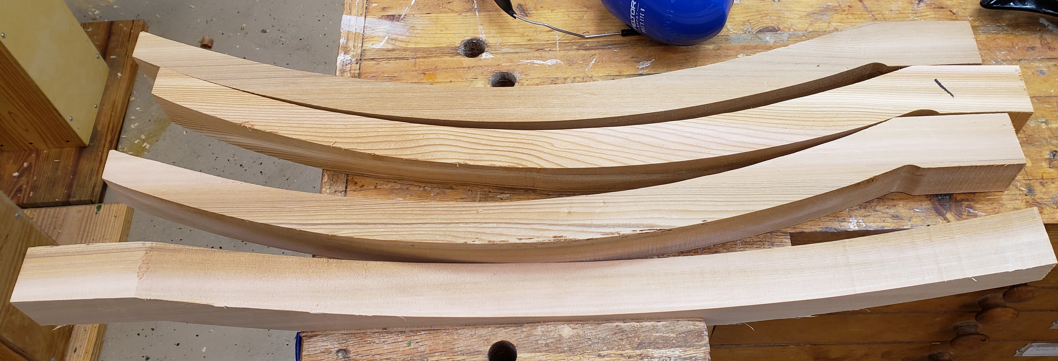
Moving on to the legs I repeated the steps used to create the initial 2×4 concept pieces only I used a pattern to speed things up. I started by roughing out each leg on the bandsaw getting as close to the line as I dared without going over. Price Is Right rules apply here.

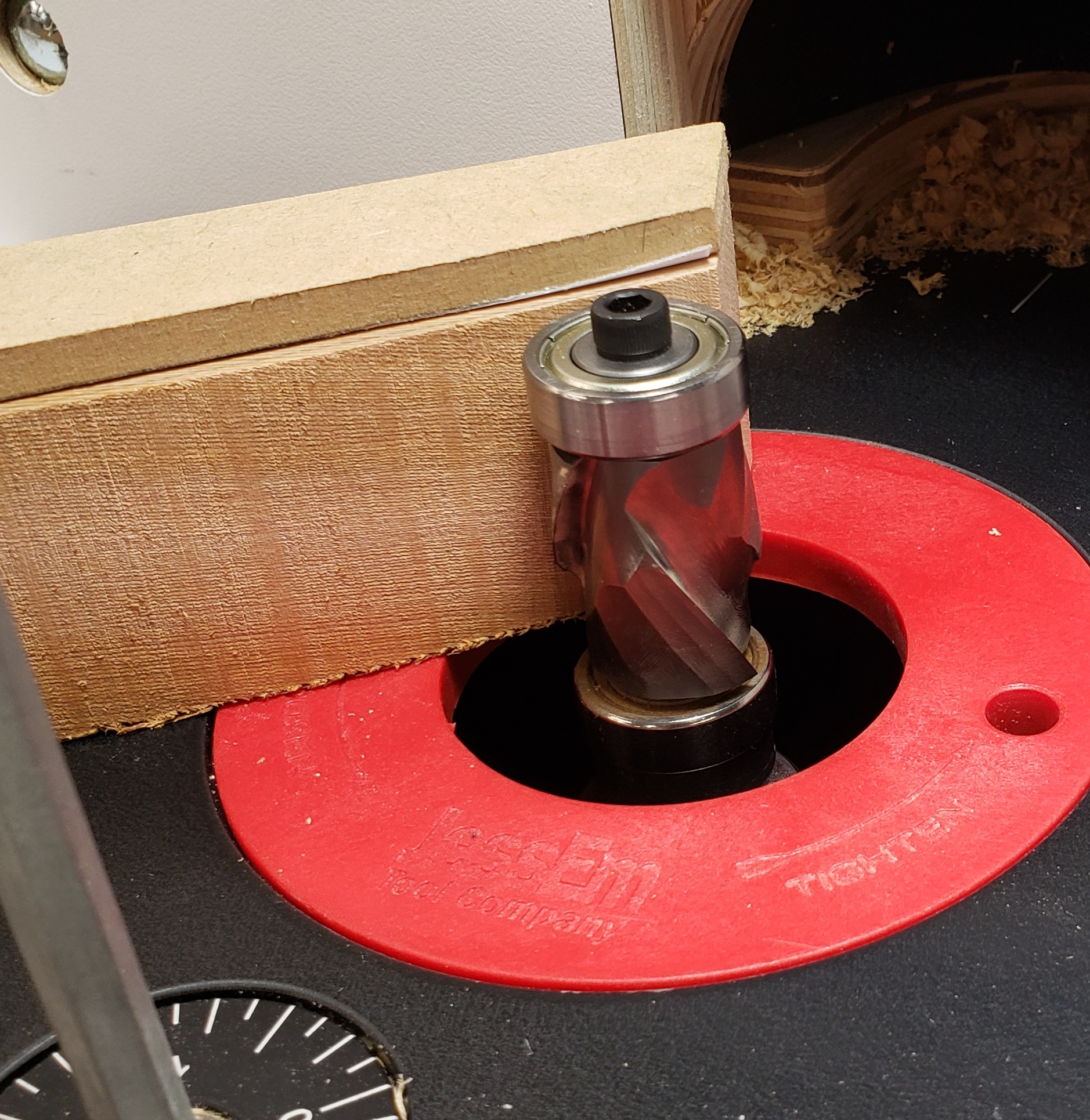
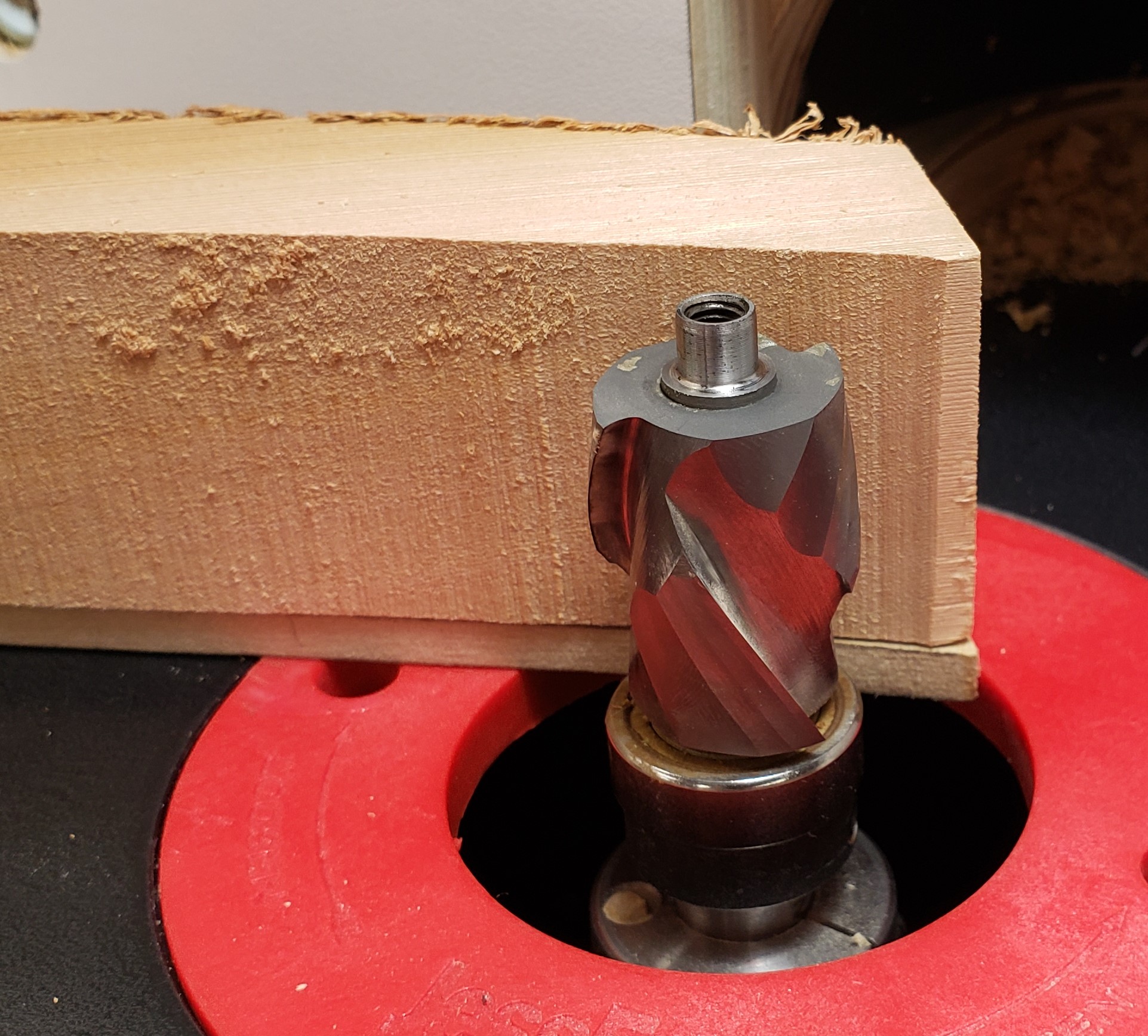
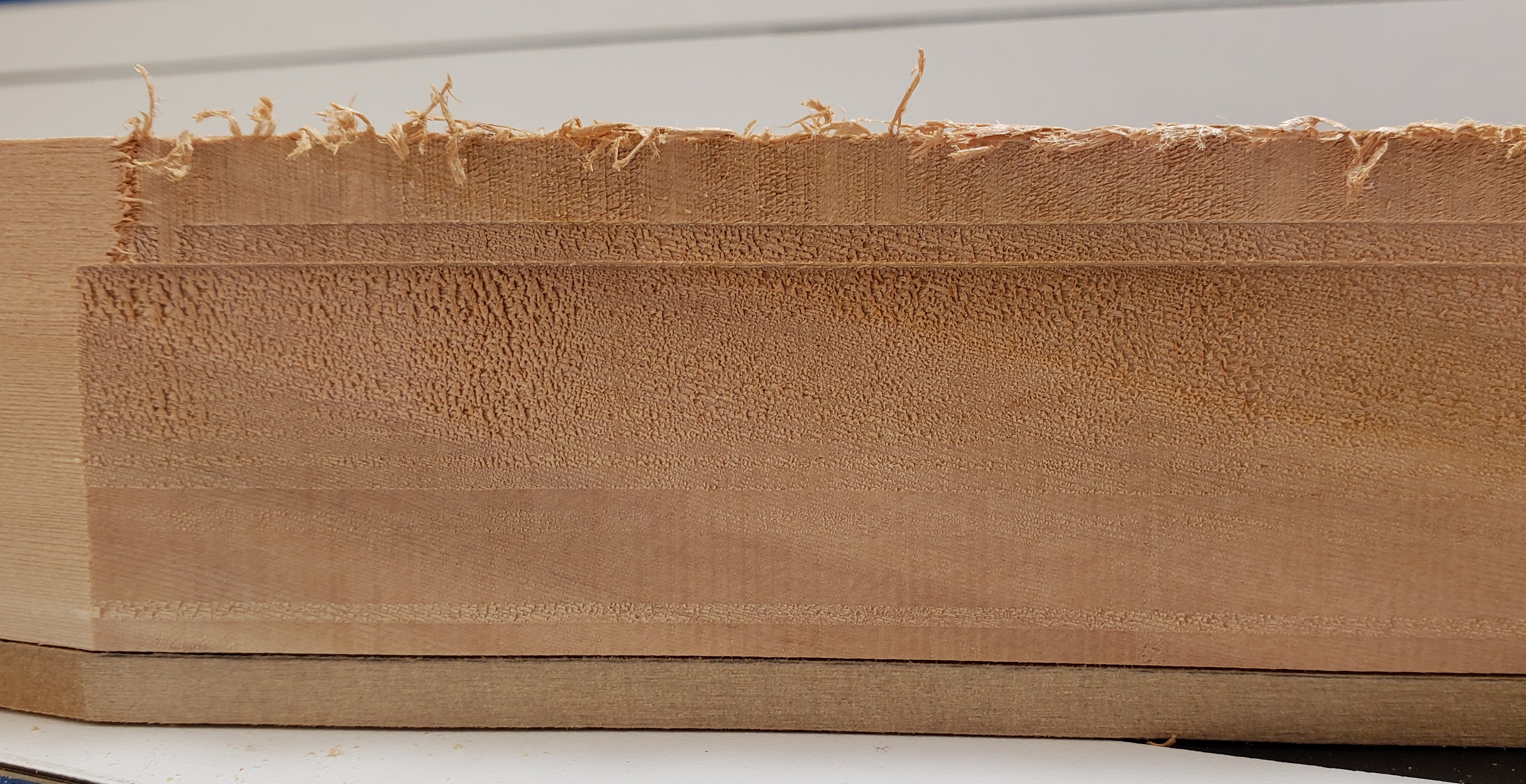
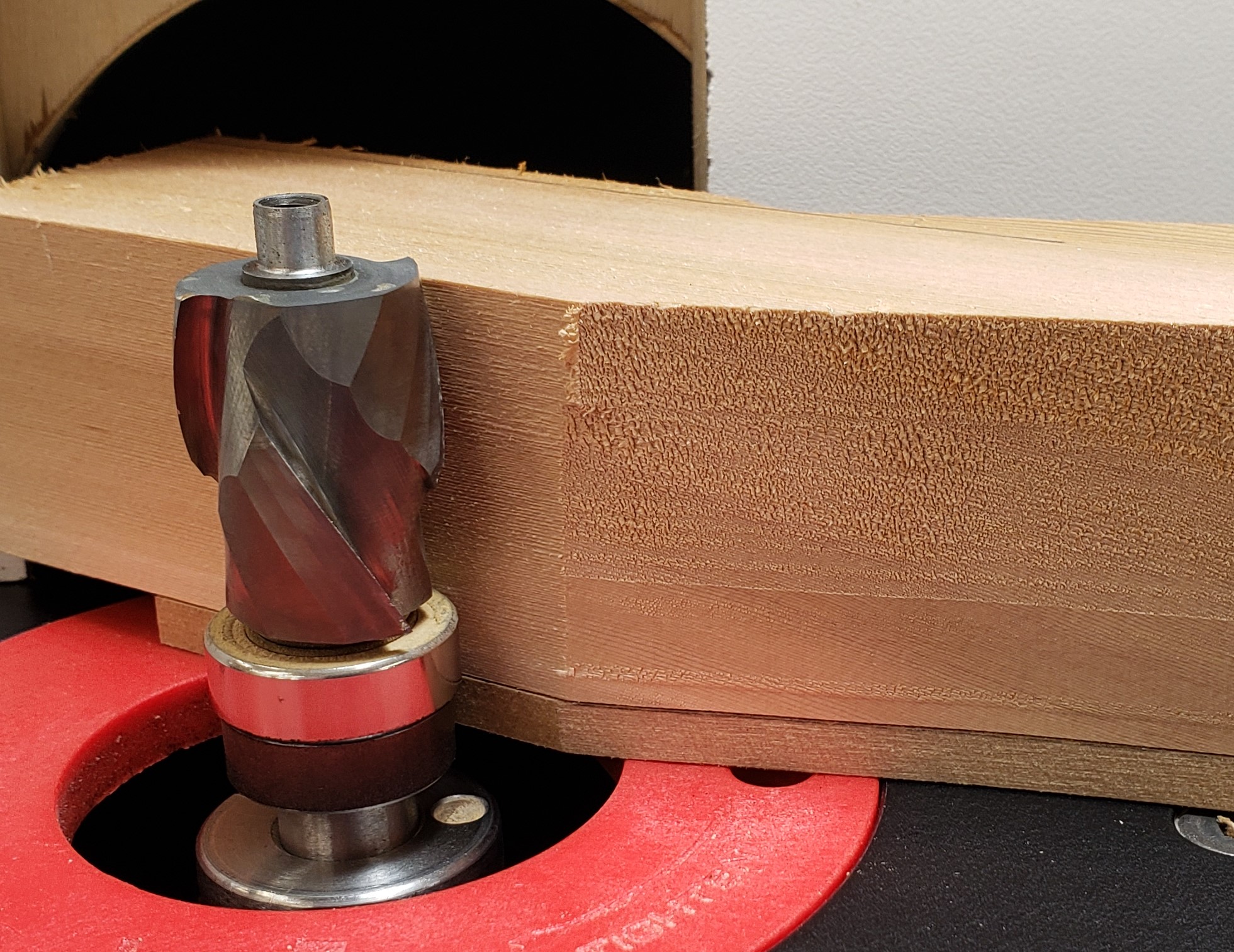
With the legs roughed I again used the pattern bit to clean them up to the line. I just bought this fancy compression pattern bit because of how much I do pattern routing. Oops, the piece is too tall to cut it all in one go. Off goes the top bearing, I will have to take one bite, then increase the bit height to do it again.

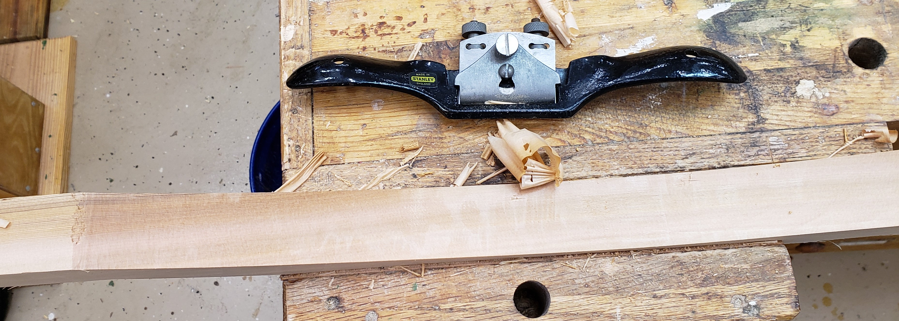
I got all the routing done, but was still left with a pretty rough surface. Cedar is so soft it tears more than it cuts with the router. I actually got to break out my spokeshave in order to clean up the leg faces. Probably overkill considering I am going to round over all the legs, but it was still fun and good practice.


Aprons and Assembly

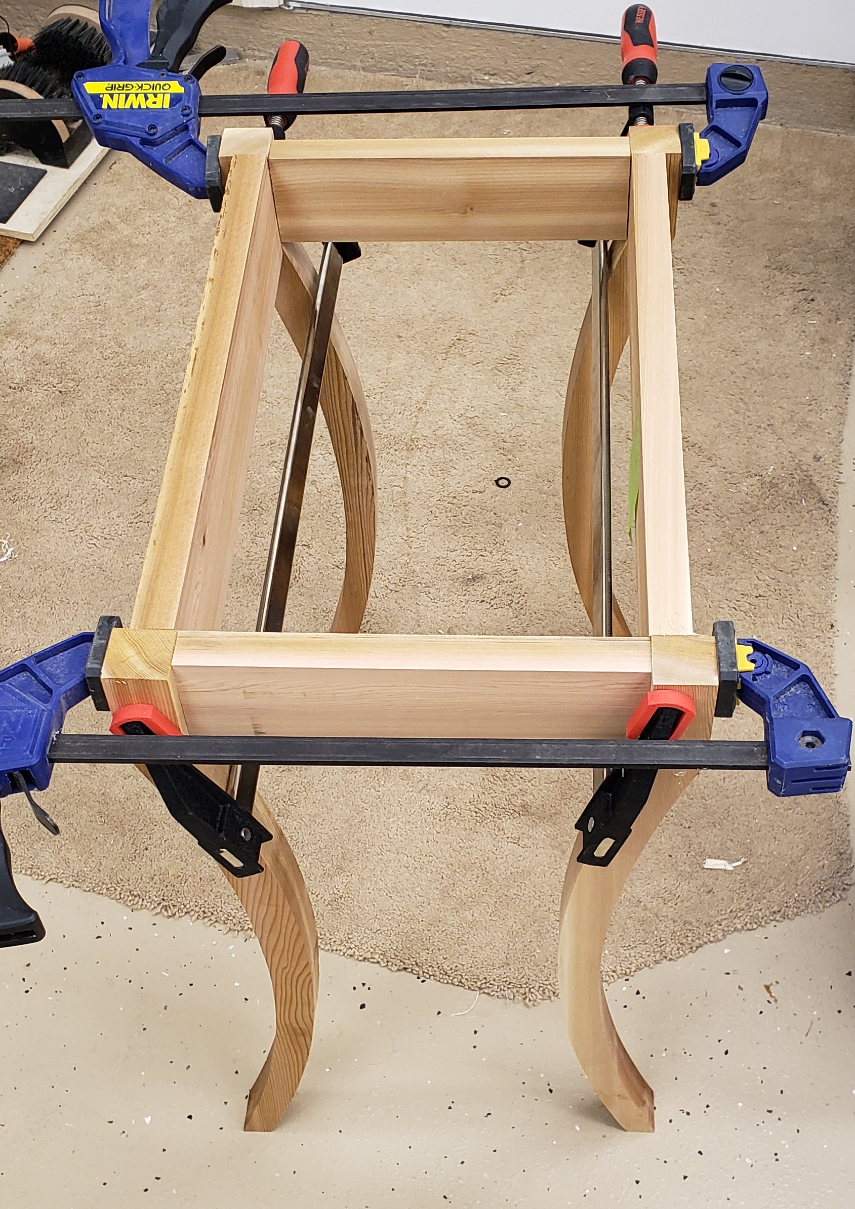
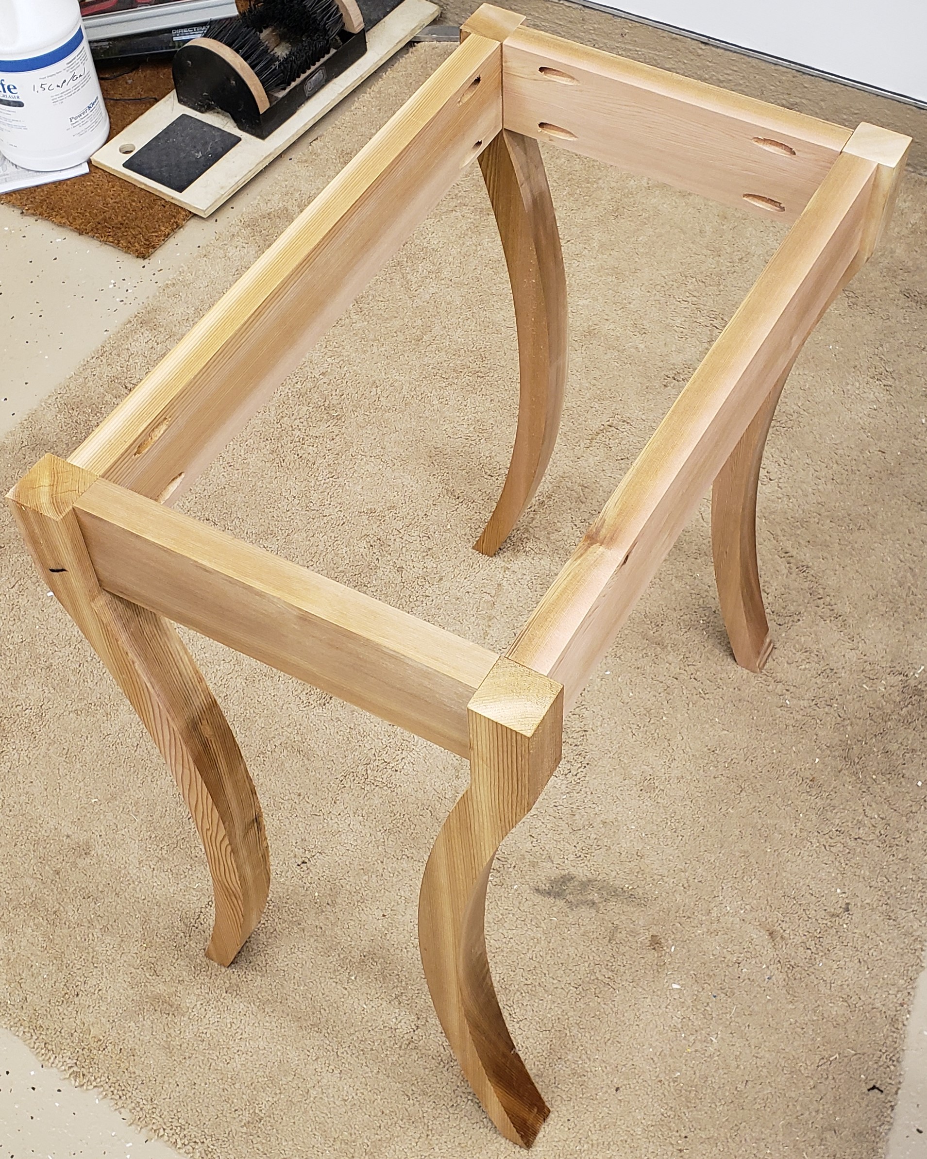
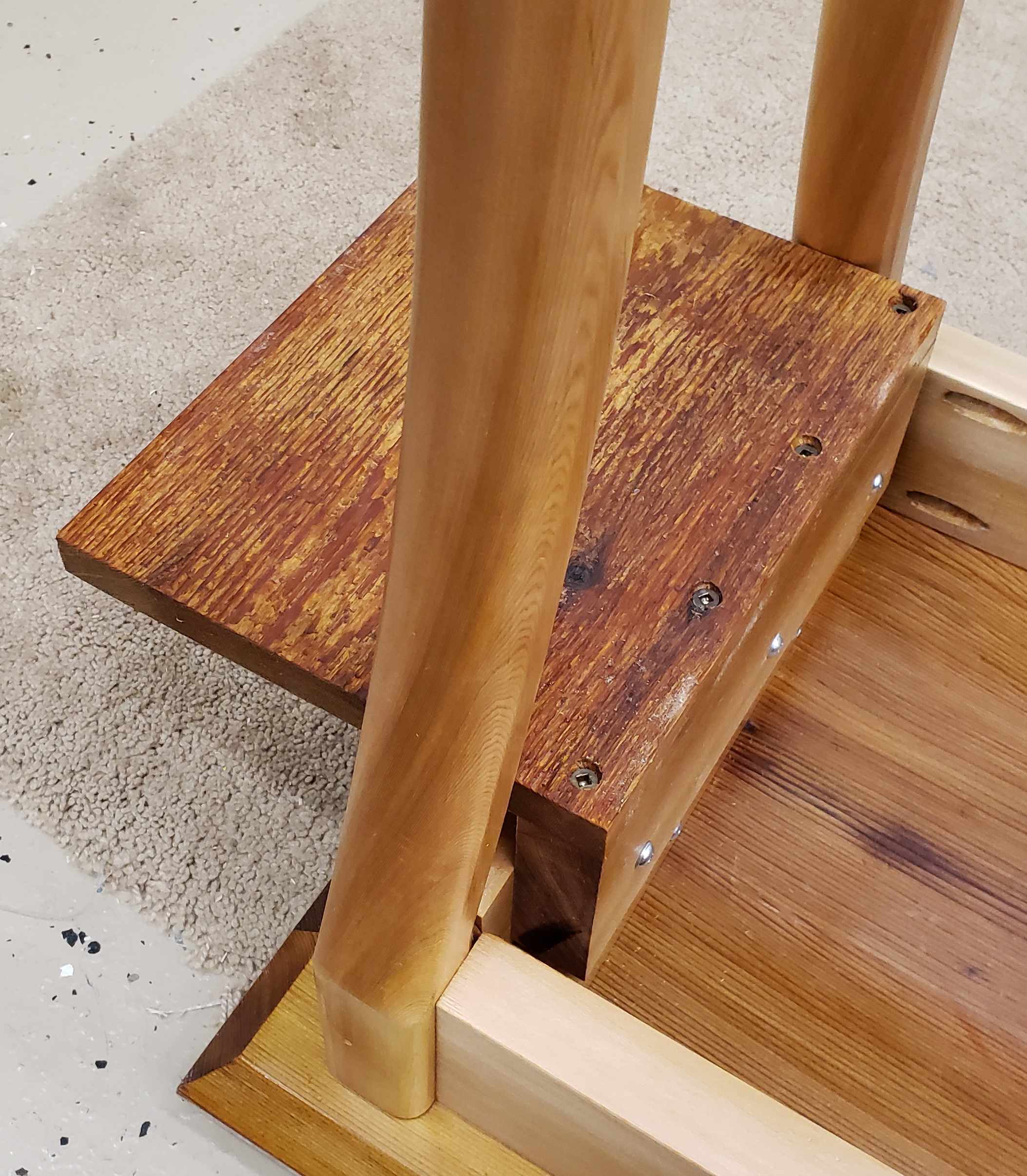
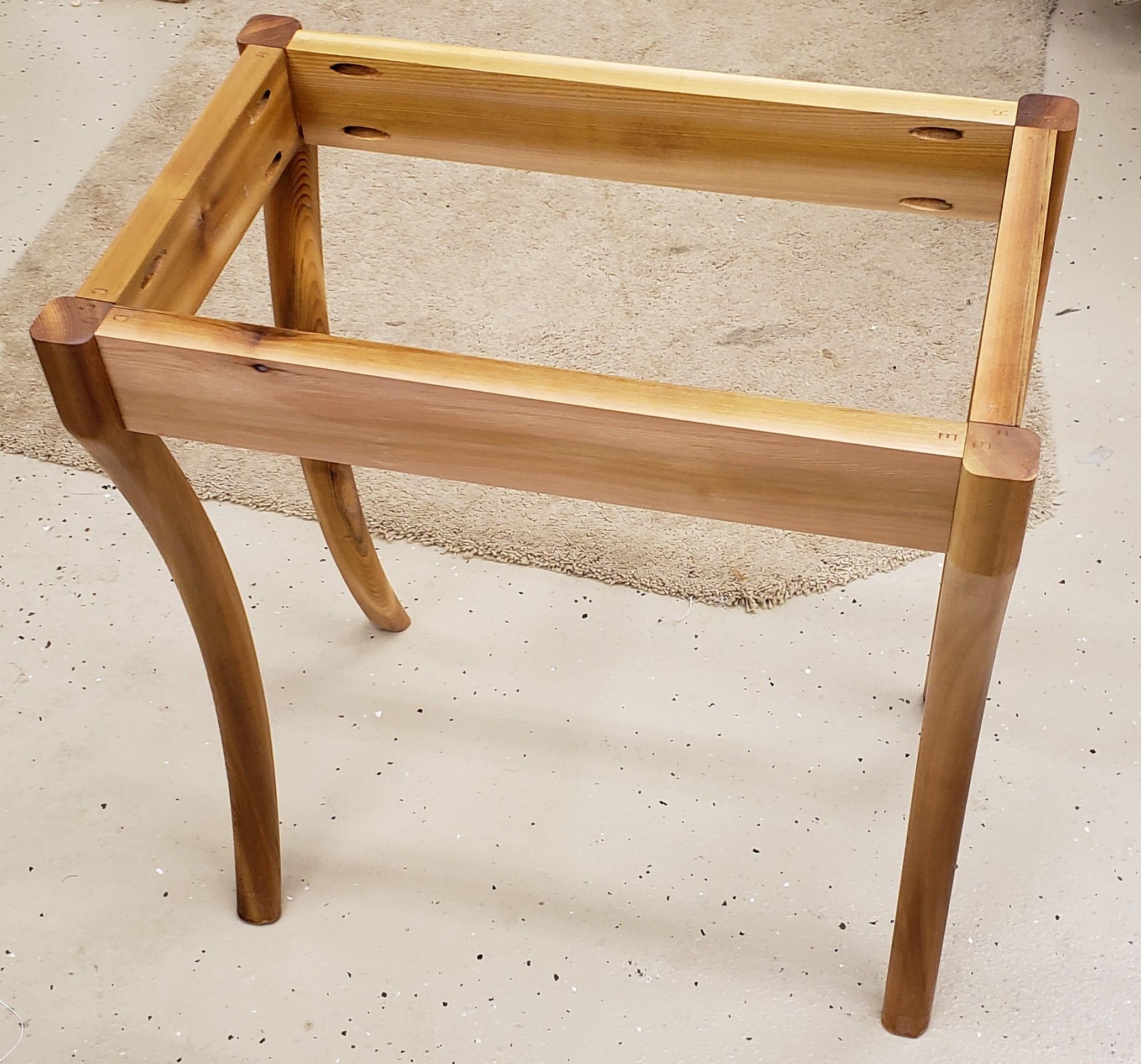
I am leaving the legs square until the last minute, they bruise like crazy and I want to preserve their shapes. Instead of trying to cut mortise and tenons I just used pocket hole screws. I would probably blow out a side wall trying to mortise these legs, and the pocket hole screws are outdoor rated.

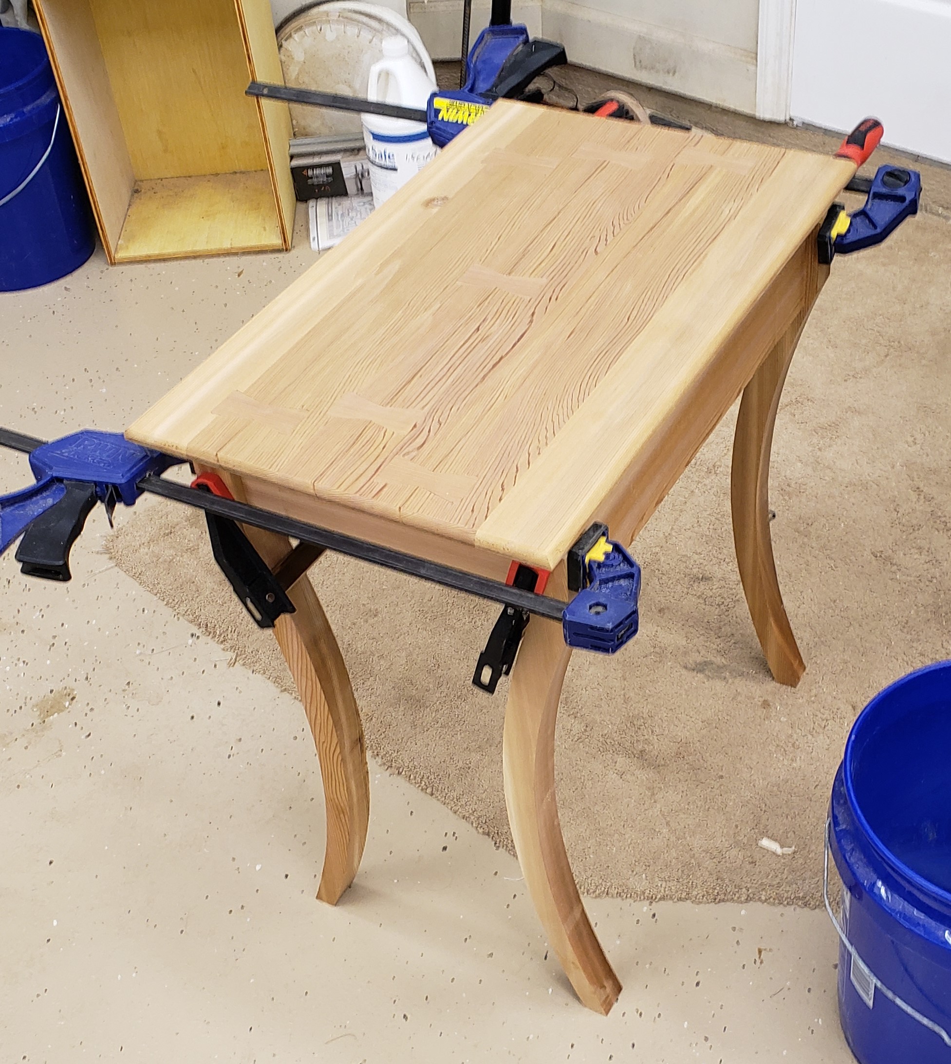
To get the shape right I cut the aprons a bit long and assembled with clamps to get a feel for the size of the base. Then, I was able to cut the width and length down until the proportions looked good. Not as fancy as drawing it all out ahead of time and knowing the exact dimensions, but better than just making up round numbers and building it regardless of looks. I am no master designer, but I am getting better. Once I got the dimensions right I drilled the pocket holes and did a final test assembly.

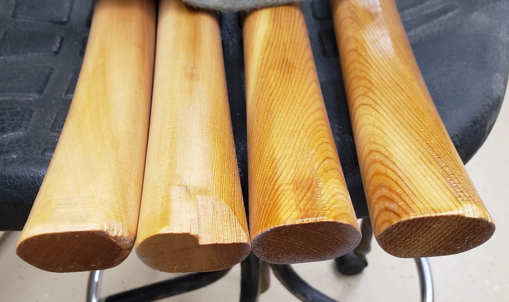
With the dimensions all set I could do my roundover on the legs and perform final sanding on everything. Once again the cedar bit me. The roundover, which I did in multiple gentle bites totally chipped out the bottoms of the legs. I could trim them down a smidge, but I figure the rabbits will chew down there anyways, so whatever.

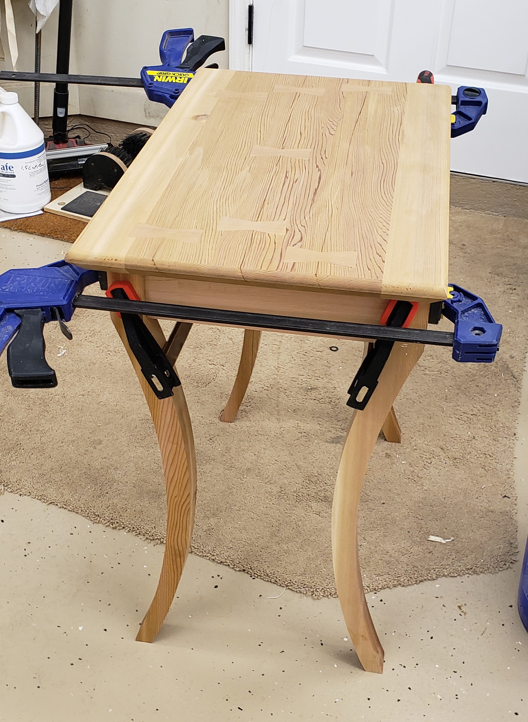
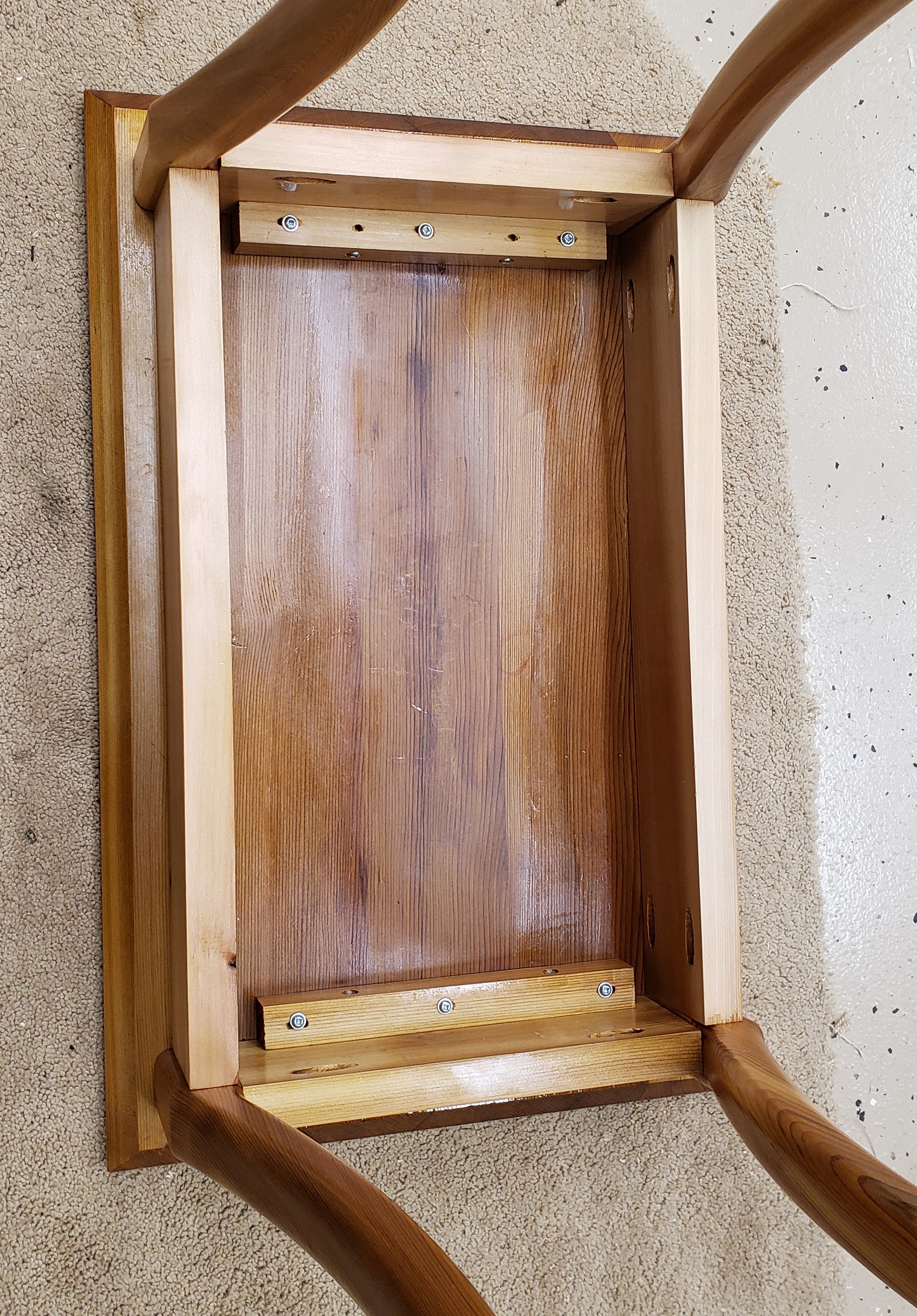
I finished all the parts individually with a spar polyurethane that I thinned down to make a wiping poly. It is dark to help keep UV damage down and it did make the wood take on a lovely color. To attach the top to the base I made a cleat with slotted holes so the table could move and not pull apart. I also added a hidden back shelf so we could sit things behind the table. Our son likes to pull out the tissue box and assault the fan remote. These can be stored in the back.

I attached some plastic slider feet to keep it from having direct contact with the ground. The table never sees direct sun or rain, and between the wood choice and finish it ought to last forever. The softness of the wood means that a child and two rabbits will destroy it mechanically before nature ever does. Done just in time for porch season to set in.

Height Growth Ruler

Our little guy is growing fast and I wanted a way to help document that. Kids are usually interested in seeing how big they are, so I decided to make a height ruler. I started back in July because I wanted to be done by the time his birthday hit. I got done in time, but hit a bunch of snags along the way, and still have trouble getting him to hold still for a measurement.

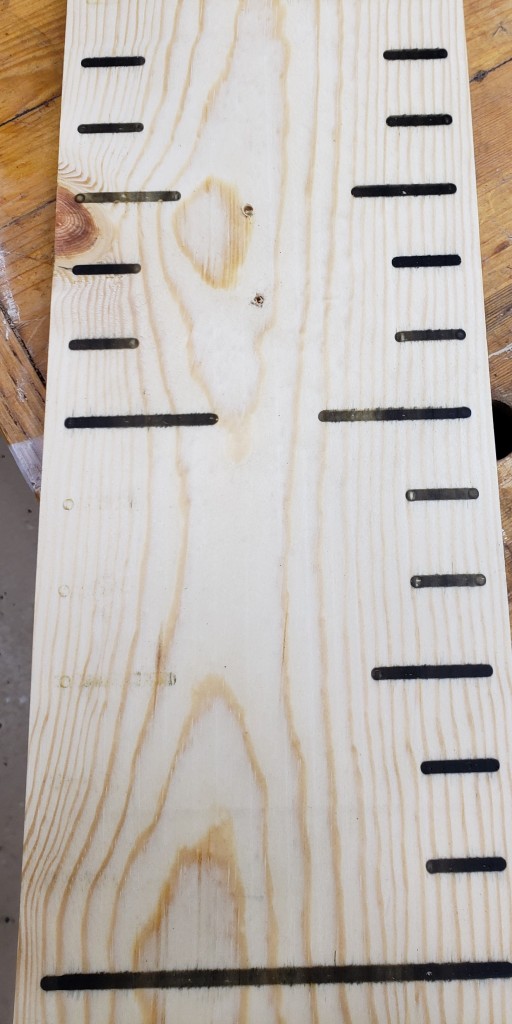
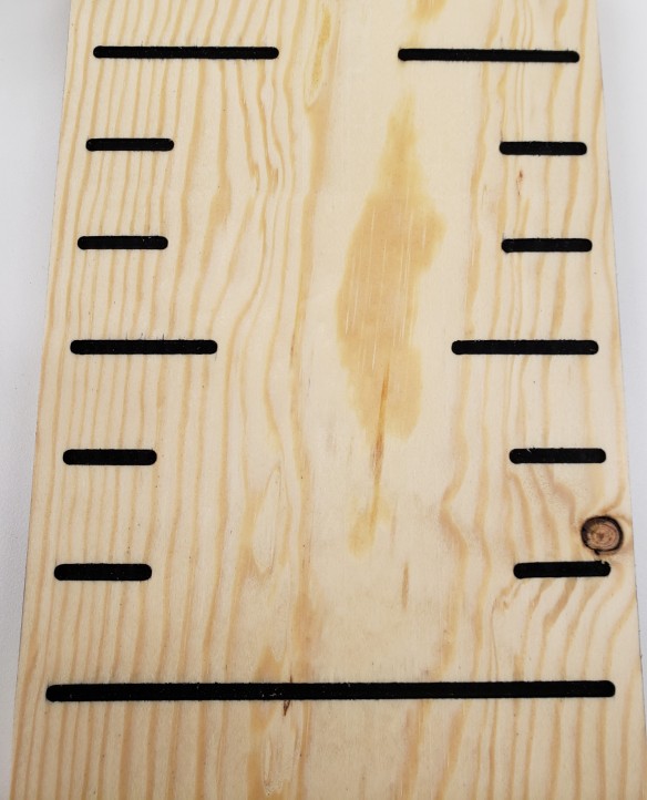
First up, I bought some pine boards to experiment on and 3D printed this guide to make the ruler marks. This took a few iterations, I was trying to use a pattern bit, but ultimately a bushing and plunge route was the best way to go. You can flip the template around to continue the pattern and route the whole ruler with one template. I based the marks off of an old folding wooden ruler I have.

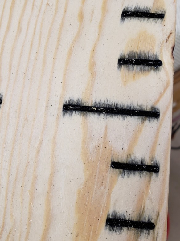
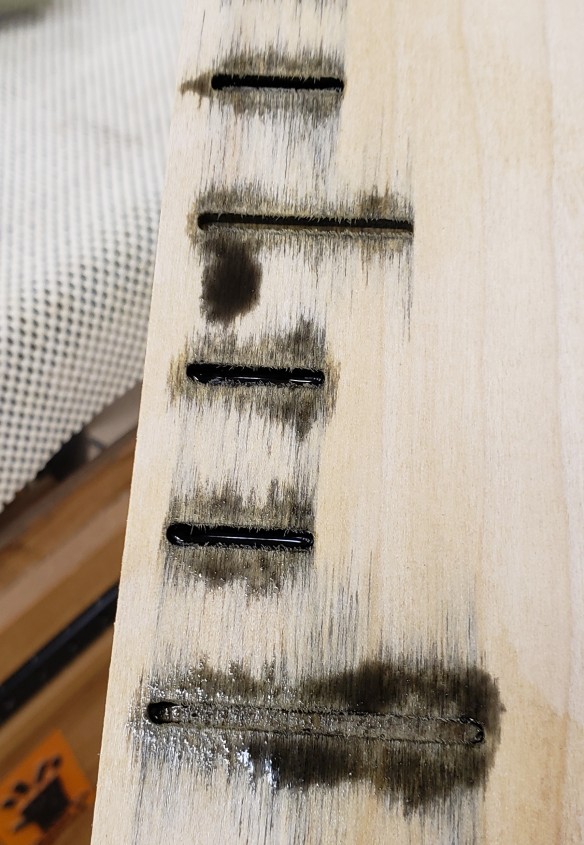
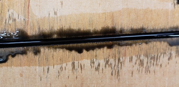
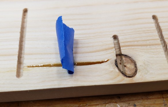
The first big issue I ran into was inlay. I wanted to route a pattern, then mix black epoxy to pour into the cut grooves. The epoxy kept wicking into the grain. I tried poplar, it wicked too.

I tried sealing the grain with multiple rounds of shellac and still ran into some issues on the poplar samples. I should have started with a hardwood of some sort.

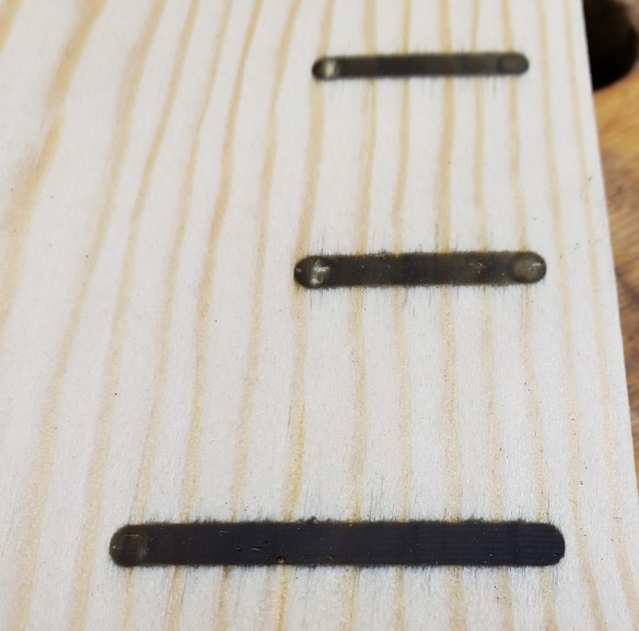
I eventually got enough sealing done on pine and filled another test piece. There was still some grain seepage and in trying to plane through the top surface and get to flat inlay, I kept hitting bubbles. I tried vacuuming the epoxy and still couldn’t get it to be void free. Here again, the rough pockets that are left by the routing might be allowing air pockets. Again in retrospect using maple or something would have been better.

Finally I settled on a quick clear coat to seal, and spray paint. It makes the router cuts dark and visible, and is easy to apply. The sample board turned out well enough, so I moved on to the real thing. I will work on improving my epoxy inlay techniques later.

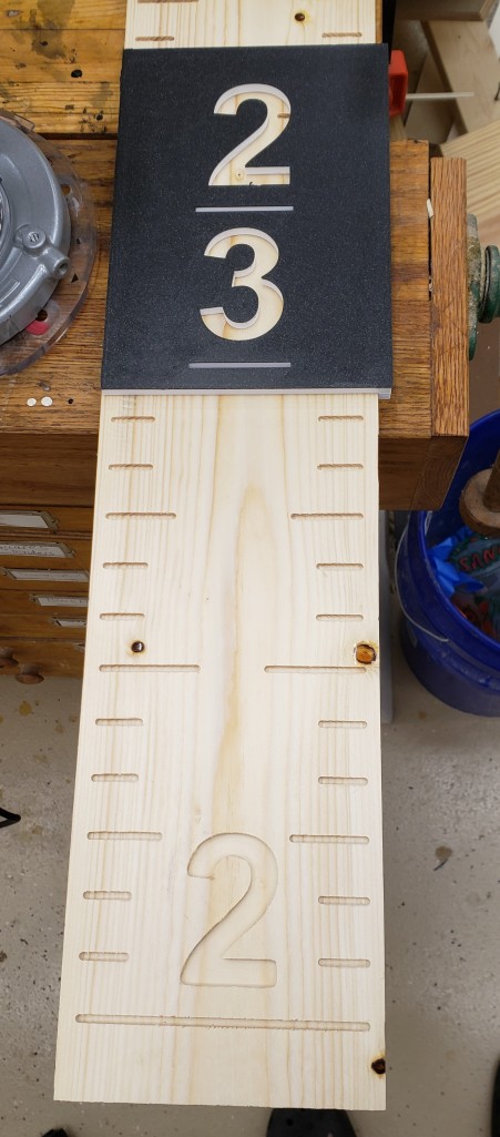
I printed letters to make the ruler clear to read. Each letter has an alignment line underneath so you can see the foot mark line when putting it down. I had a few knots and checks that were in the way so I used clear epoxy to fill the voids so that the spray paint wouldn’t get inside. I then routed everything and sprayed the entire surface.

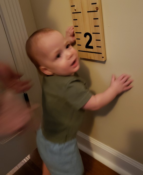
I planed off the top surface to reveal a decent inlay. Everything got a few coats of finish, then hung up on the wall. The hardest part now, is getting him to stand next to it. He pulls himself up to standing constantly, but always has his own agenda. This picture was the best I could get in nearly 2 months of trying. Never work with kids and animals they say.

Nuka Cola Sign

I have been a fan of the Fallout video game series for a good 20 years, since I first played the original game. Sometimes called Diesel Punk, imagine a retro-futuristic world imagined in the 1950s. Everything is nuclear powdered, sleek ray guns, cute suburban homes with tv dinners and a cold war that went hot. The game has a lot of back story and atmosphere including a soda brand called Nuka Cola that looks a lot like coke.

I am also a fan of this funny Russian guy that makes signs with lots of skill and few tools. He did a few different fallout based signs, so I had to follow his lead and make my own Nuka Cola sign. His methodology is simple. Project onto a piece of plywood with a cheap projector, trace, carve those lines in with a dremel so you can see them after you paint, then paint the various layers. I still managed to mess up a little. First up, the projection.

I found a rough text/logo of what I wanted and used inkscape to make the offset for the sign outline. I hand traced it and moved on to cutting the outline. It took a little special sanding to get it all straight and clean, but I was happy with the shape.

Next came the carving and a bit of an issue. The plywood I used was pretty light and I had trouble seeing how deep I was carving. I started with a small pointy burr, and moved to a much larger, too large, ball carver. Later when I painted it all, everywhere I touched was obvious, and the deeper cuts were obviously too much. Next time I might prime with a neutral color before starting the projection. It will make the pencil line standout better, and make the dremel lines more obvious.

With it painted, the base red coat it might be a bit more obvious how uneven some of the carving is. The jigsaw guy mostly back sprays with black to form a border. I did that too, but the complex shape in a few spots means I will have to go back and do it again after putting all the red down.

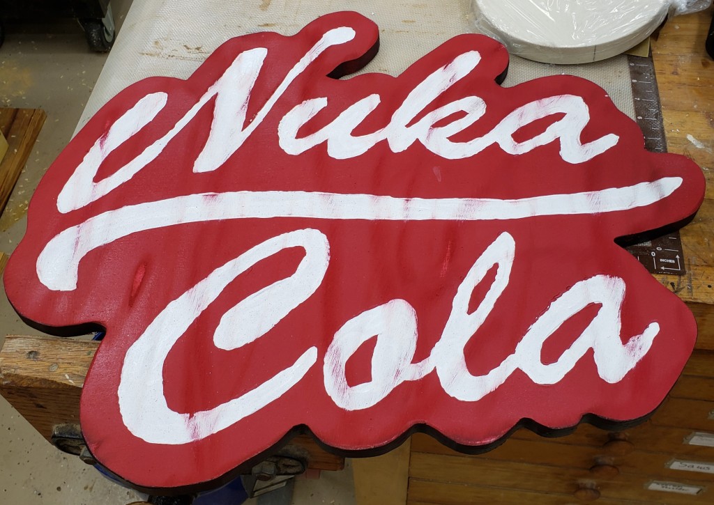
With the base of red down, you fill in the letters with white. I went for house paint and did 3 coats. It built up more texture than I wanted, a good quality craft paint might have been better. In the end it didn’t matter that much. The biggest issues was my wobbly carve lines that were too big in places. It kept my edges from being very crisp. It is hard to paint to a clean line when the guide is over an 1/8″ wide. A weathering trick he uses sometimes is to hit the finished product with a wire brush on a drill. Genius, it looks great.

Overall I am really happy with the project, but I need to work on my dremel carving technique and hand painting. I have another sign idea in mind, so hopefully the lessons learned will be applied there. It looks great in my shop next to a metal fallout sign I got ages ago.

Disk Sander Circle Jig

My Bandsaw Circle Jig actually started out as an idea for a disk sander jig I saw in one of my woodworking magazines. They used a sliding arm with a screw adjuster to fine tune the diameter of the circle. I thought this was neat and it slowly evolved into the arm I made for my bandsaw jig.

I already had an arm with T-slot track in it from the bandsaw project, so I figured that would get used in both jigs. You could cut on the bandsaw, then fine tune on the disk sander. The construction method I used before applies well here too. 3D print a runner to go in the miter slot, start with a base of 1/4″ MDF, then attach 3/4″ MDF on top to guide the sliding arm. I CA glued the runner in place with it all aligned, and then screwed it in from underneath.

I don’t have any features to keep the adjustment arm locked down because the disk sander’s movement should push the work piece into the table and keep it stable. Hopefully that theory continues to work out for me.


The new thing here is the adjuster. The wood magazine had something with a T-nut and bolt. It was fine, but I figured a printer could do better. The knobs were something I had designed earlier. Each holds a 1/4″-20 coupling nut. The adjustment screw is a bit of threaded rod with a coupling nut bonded to one side. The other was rounded via a drill and bench grinder. The knob will glue on to the nut and the rounded end will push up against a hard stop. Having it rounded should mean there is only point contact and will make for smoother more even adjustment.

The adjuster uses a bolt in the t-track of the adjustment arm to clamp itself down in the rough position. I added a block to the bottom of the jig and bonded a big fender washer down for the head of the adjustment screw to contact. It should be a very firm stop and won’t wear easily.

Putting it all together, and with a few coats of polyurethane to keep the MDF stable, I tested it with another sharpening wheel. My last one was a little small, so I made a new bigger thicker one. The only thing to note is that doing heavy sanding in one spot will load up the paper badly. Sliding down the table occasionally will help even out the wear.

Bandsaw Circle Jig

I have a router circle cutting jig from milescraft that works pretty well. It screws down a center and uses your router on an adjustable arm to make big circles. It does take a bit of setup though, and anything under about a foot in diameter is pretty awkward. There are loads of bandsaw jig ideas, so why not add mine to the pile? I think I have three things that are slightly unique in this design. Not revolutionary, but a bit different.

1. I started with a 3D printed miter slot runner. It is T shaped so once you slide it in the jig can’t come up off the table. Most folks make wood runners. Those are fine, but with printing it is a lot easier to dial in a T-slot so that the jig can’t lift. It comes with countersinks for #6 mounting screws.

2. The jig needs some kind of sliding arm to hold the piece being circle cut and set the circle radius. Dovetail slots and all sorts of things are employed. I took a T-track and glued it into a piece of 3/4″ MDF. Even 1/2″ screws would have been too long, so I just used epoxy. It holds well. A look from underneath shows that a bolt and knob let you lock down the circle radius arm in position.

3. To hold the work piece, most jigs use a small nail sticking up from the adjuster arm. You would drill a small hole in the part and pin it on the nail in the jig. Instead, I wanted a more flexible solution. I cut a 1-1/4″ hold in the end of my adjustment arm so I could put in 3D printed holders. One is 1/2″ in diameter so I can cut a MDF circle for my buffer. The other has a countersunk hole so I can screw a small #6 screw into the work piece. Optionally, there is enough space there to double sticky tape the puck down and use the center hole for alignment. I can print all sorts of posts or pins to suit my cutting needs.

To put that all together, a piece of 1/4″ MDF was CA glued to the runner (temporary) and pushed into the saw till it reached the middle of the jig. I glued a little stop in front so it would hit the bandsaw bed and stop in the same place every time. I then glued on 3/4″ MDF around the centered adjustment arm. That gave me enough material to screw on, from underneath, the glued runner. That all got pushed in again to the saw to cut through the new 3/4″ MDF.

I did some measuring, marked our the rough radius locations, and coated everything in a few coats of thinned polyurethane. It struggles a bit with anything under a few inches in radius, but a different blade would help. Up to 2 foot circles are possible. Above that and I will go to the router jig. To try it out, I made a sharpening wheel for my buffer out of 3/4″ MDF.

  1. Set the runner to the appropriate radius and lock the knob
  2. Install the square of material to be cut on the peg
  3. Push into the saw until you hit the stop
  4. Slowly rotate all the way through the circle
  5. Done!

Modular Buffer Stand

While I was building my Anvil Stand I was also building this buffer stand. I love my bench grinder stand to death, and want to have my other grinder setup as a buffer full time. I read about a chisel sharpening technique called unicorn sharpening, and it calls for a buffer. I tried it, and it worked well for me!

I made a basic box shape out of 2x8s (pricey these days) and attached them to a piece of 2×12 left over from the anvil stand as a base.

For the top I made a template out of hard board and labeled it with the orientation and hole info. Every tool base base that goes on top will have two T-Nuts embedded in them so 5/16″ bolts can come up from underneath to attach. That way you are always 2 bolts away from taking a tool off an installing a new one. I keep the template attached to the back of the stand so I can easily add new tools in the future.

Like the bench grinder stand I clad the cavity in plywood and filled it with sand. This shot is of it 2/3rd full, I had to go back to the store and get more sand because of all the filled projects I have been working on.

So I don’t have to go to the toolbox and remember which wrench is the right one every time, I made a palm wrench that fits the bolts. The bottom is rounded to make it easy to rotate in your hand for fast installing, and the outside hex shape lets you get good torque on it. A print like this can be surprisingly strong without any modifications and only 20% infill.

The buffer is all ready to go and looks great. It is weighty and stable while in use. I only have one tool attached now, but might get another grinder or buffer in the future. When I do, I’ll make another base and hang the unused tool off the side or back of the stand. Boiled linseed oil finished everything off.

Anvil Stand

I haven’t done any armor creation or blacksmithing in a long time. That said, I still have the anvil and other tools for it. I have the anvil strapped to a piece of 2×12 that usually gets put either on the ground, or screwed to a bench for temporary use. It comes in handy for trying to tap something back together, or for banging out something. I felt after all these years it needed a proper stand at the right height.

I measured the distance from the ground to my hand while wearing my shop boots and designed a basic box structure to hold the anvil. I made the base the width and depth of the already existing wood it was attached to. No reason to re-do that, it has been very successful.

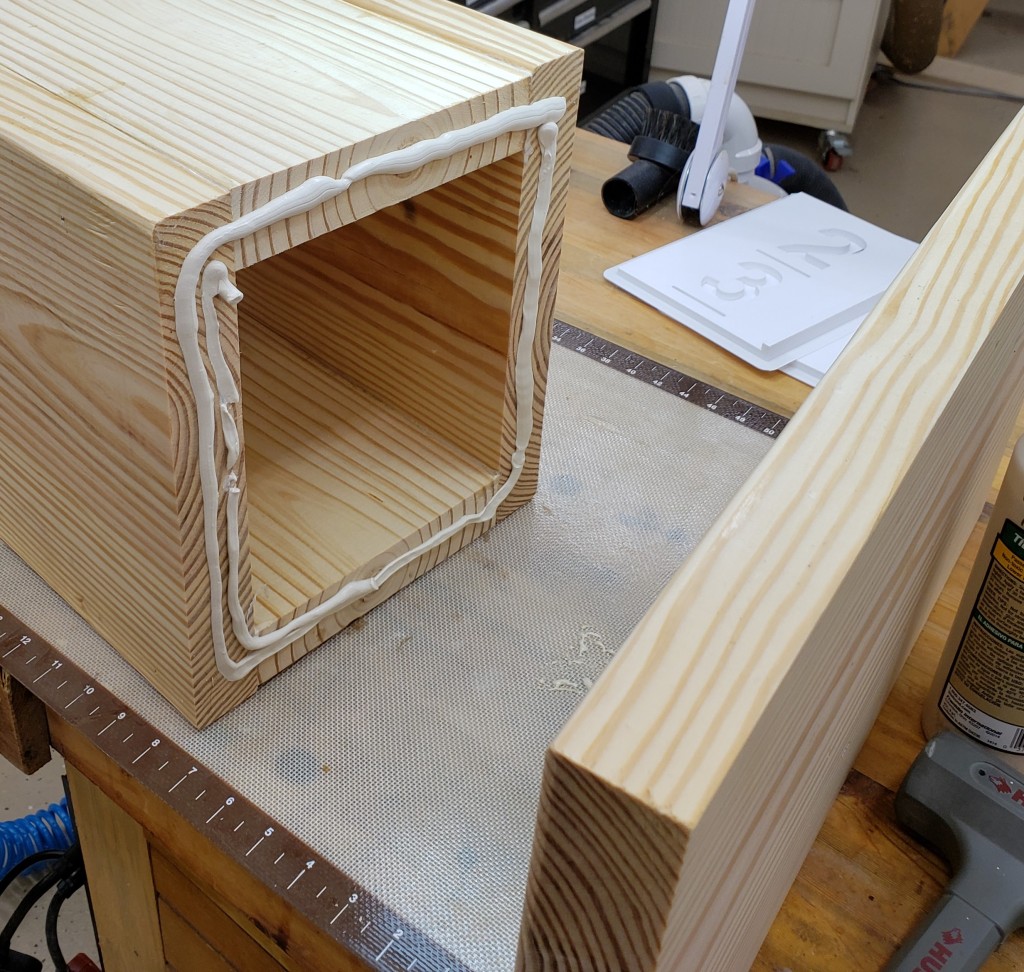
I added a foot to the base. It sticks out the front so that if I am hammering away on the front of the horn, the whole thing won’t want to tip forward. Weight and stability are what we are after. I attached it with screws and construction adhesive to make sure no sand leaks out.

When the glue from the sides and the base all dried up I filled the center cavity with sand. It is cheap, adds weight, and helps deaden vibrations. I put in a whole 50lb bag, plus some extra.

I estimate it is about 30 pounds of wood, 60+ pounds of sand, and the anvil is 55 pounds. At roughly 150 pounds, this thing ought to stay put when you smack on it. I attached the top and had a usable anvil stand.

Last but not least I added my favorite shop finish, boiled linseed oil. Cheap, effective, and pine looks great after a few years of aging with it on. This thing will look really aged by the time Ira is old enough to ask about it. Maybe I will make up some story about it being rescued from some ancient site. That should work till he notices the epoxy coated torx head screws I used to assemble it.