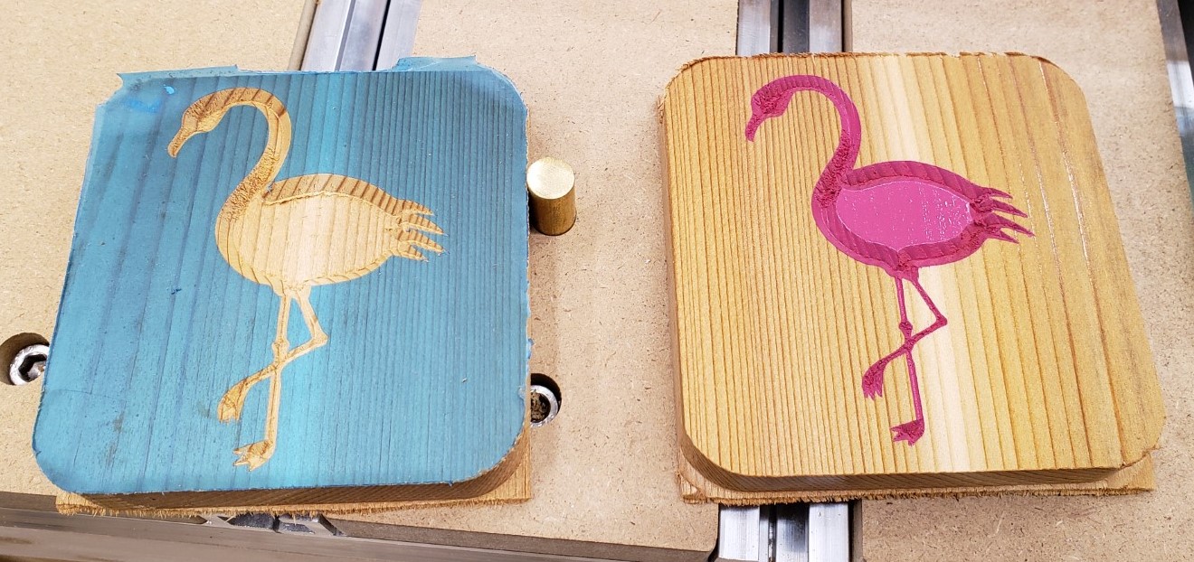
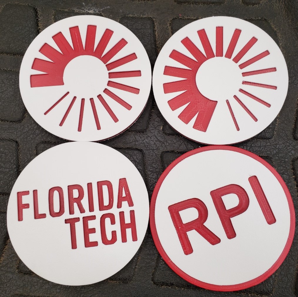
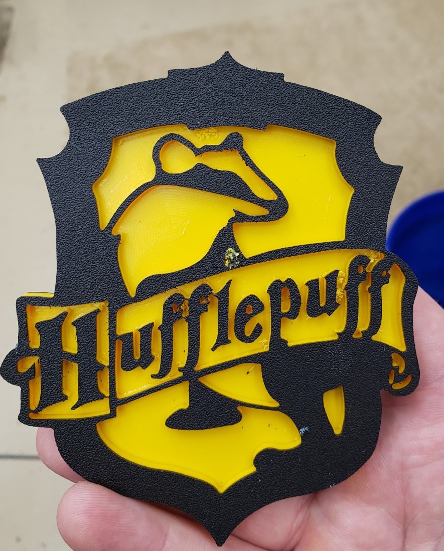
Updates have been few and far between recently. Being a toddler parent doesn’t afford me a lot of time in the shop, and the learning curve has been steep on the mill. That said, I have gotten a lot craftier with it and have fusion 360’s complicated CAM system pretty well whipped. I built a set of drawers for my mill and in the process created multiple versions of a joinery jig, and even dove into python code to post process my g-code. It will take a few posts to unravel it all. First up, a few shots of random fun coasters I made the past few months.
The Drawers
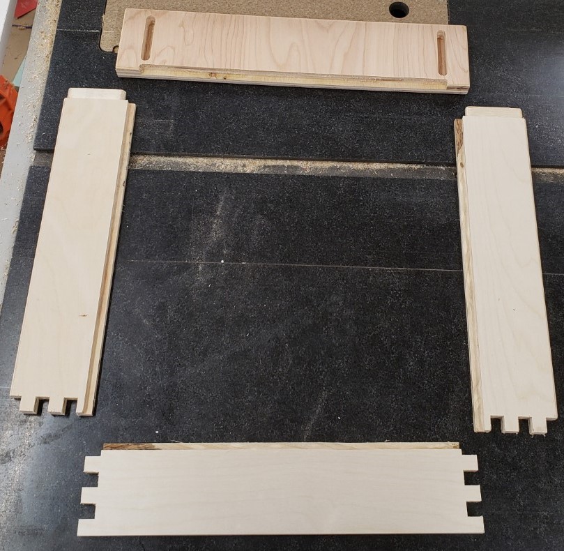
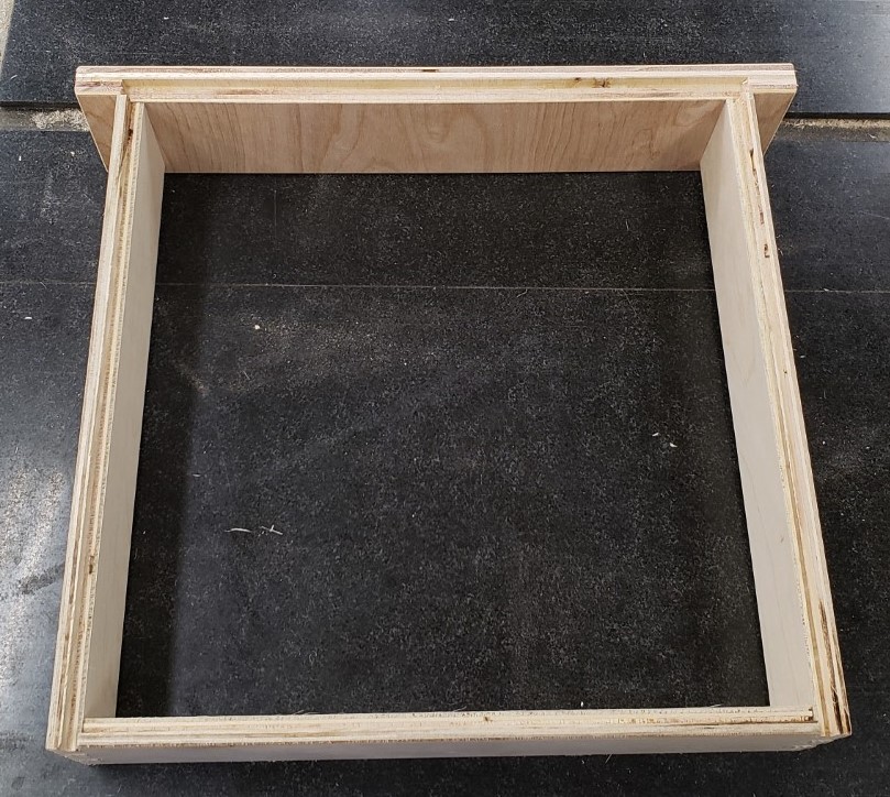
What kind of drawers are we talking here? Nothing too fancy, but I wanted the ability to make finger joints without too much fuss and setup. I’ll leave the details of the joinery and lessons learned for another post. For now, this one has finger joints on the back, and a tenon into the drawer front for the sides. Hidden and very strong.
Jig V1
The first jig was a pretty simple setup. I attached a piece of plywood to the front of the mill table to align boards vertically to the table. It was square to the top and had cam lock clamps to hold the board in place. Sticky backed sandpaper provided secure grip on the table side and on a clamp board. I had a double layer of plywood screwed down to the table behind the board to back the cut and a plank of 1/4″ MDF on the font. This gave both sides of the cut support to prevent blowing out any drawer side pieces.
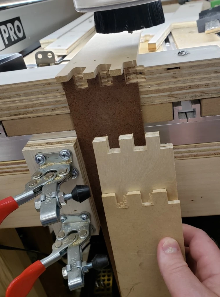
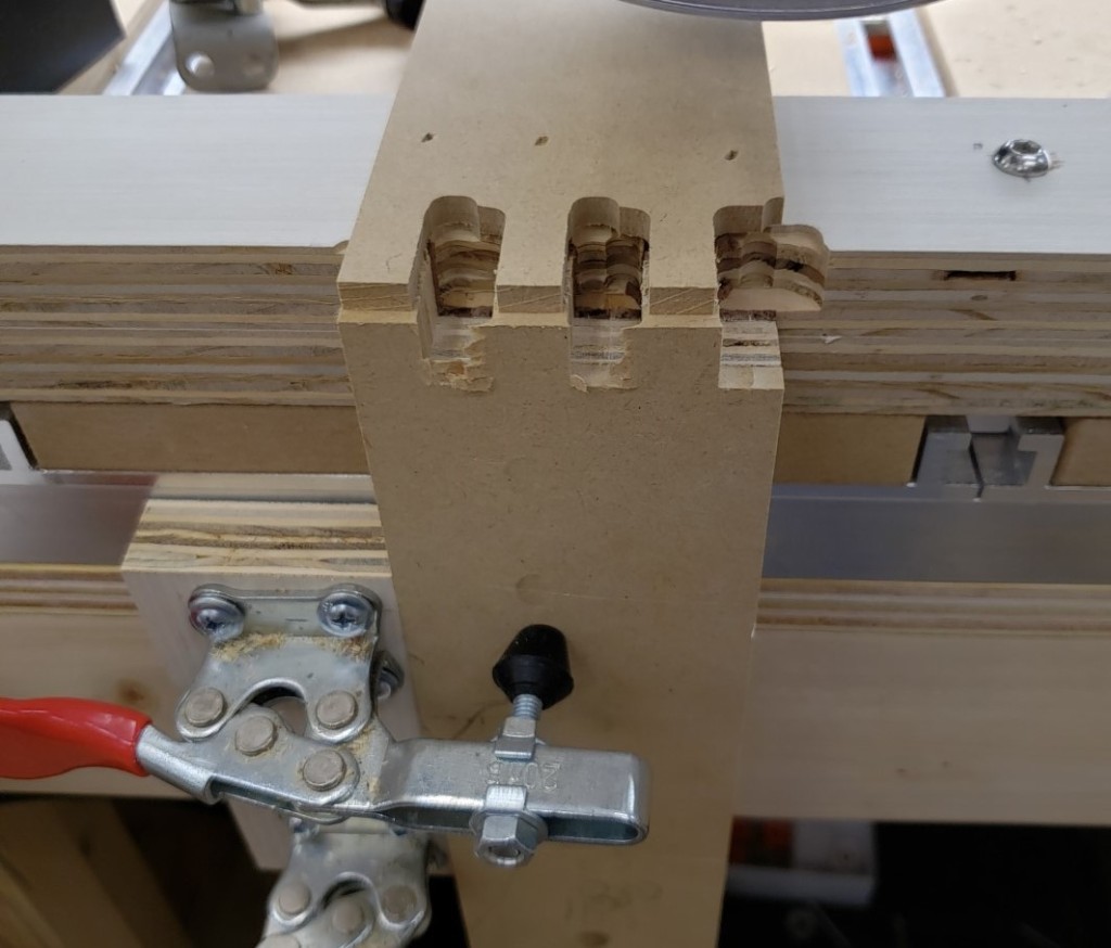
With this setup you could repeatably clamp a board in place and usually get a pretty good cut without too much fuss. Replacing the backer was a huge pain, and the top stop was only good for one shape. It worked for my first 3 drawers, but after that I stopped to think of something better.
Joinery Jig V2
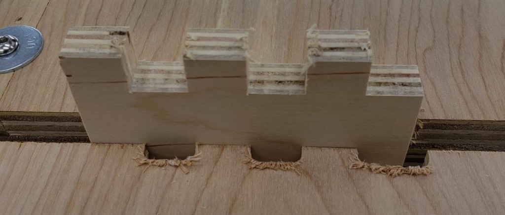
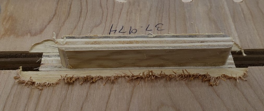
The next version has a two half system. The back half bolts down to the table top while the front half slides and clamps the board to be processed. There are sacrificial inserts that back all of the cuts to prevent blow out. Those are held in place by two clamp bolts on either side.
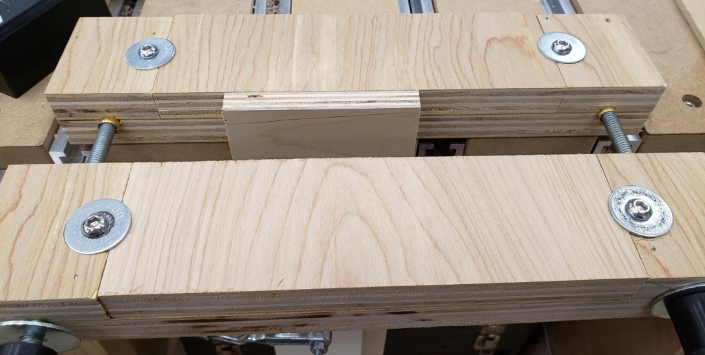
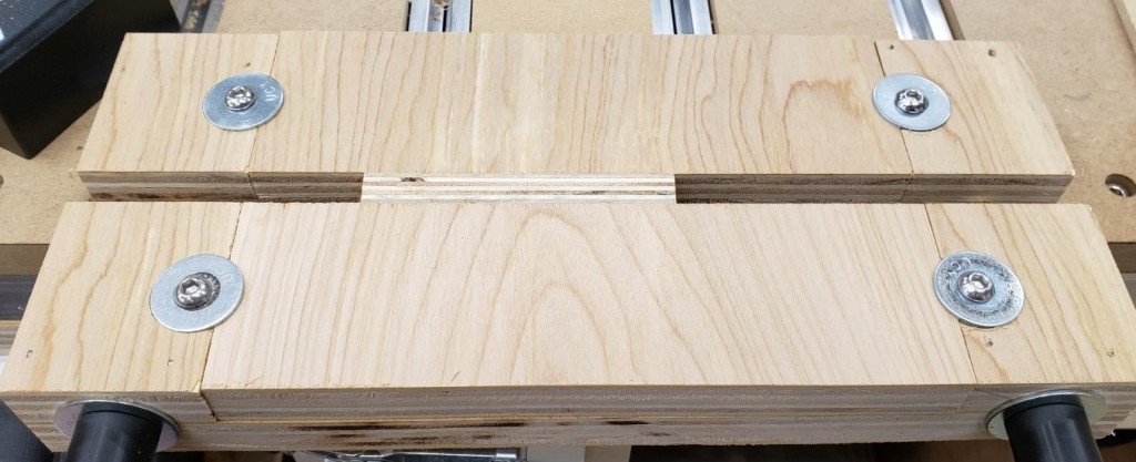
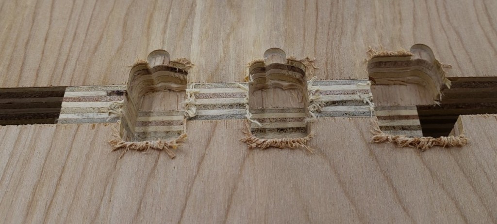
To create the jig I attached two pieces of 34″ plywood to the outside edges of a larger piece of plywood with glue and nails. This would be the base area for the rails/bolts that clamp the two halves together. I will mill it all as one piece and cut it in half at the table saw.
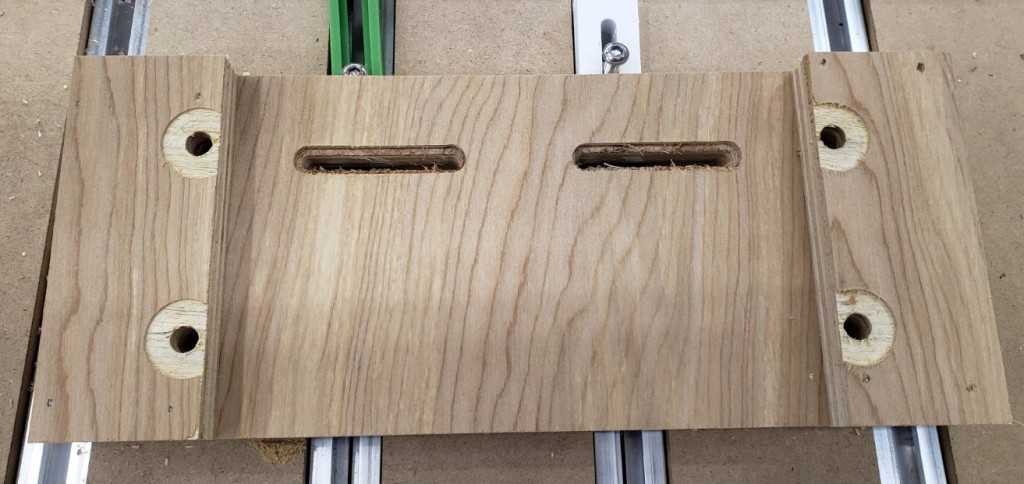
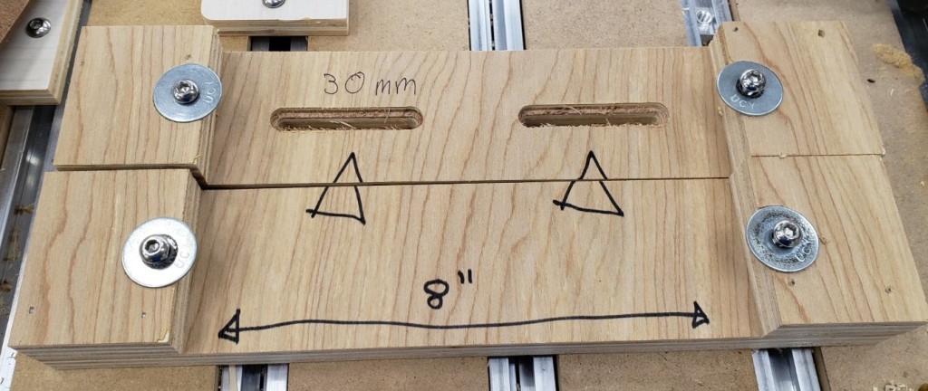
The slots are 50mm long and spaced 100mm apart. That should let me position it anywhere on my table top by always spanning two rails. I started with them just wide enough to hold the bolt head, but eventually widened them to allow washers. Bare screw heads on plywood would eventually compress and allow the jig to rotate.
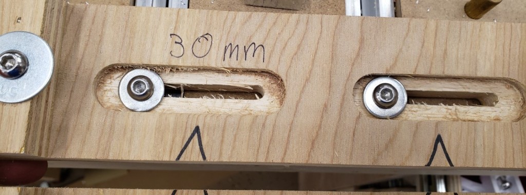
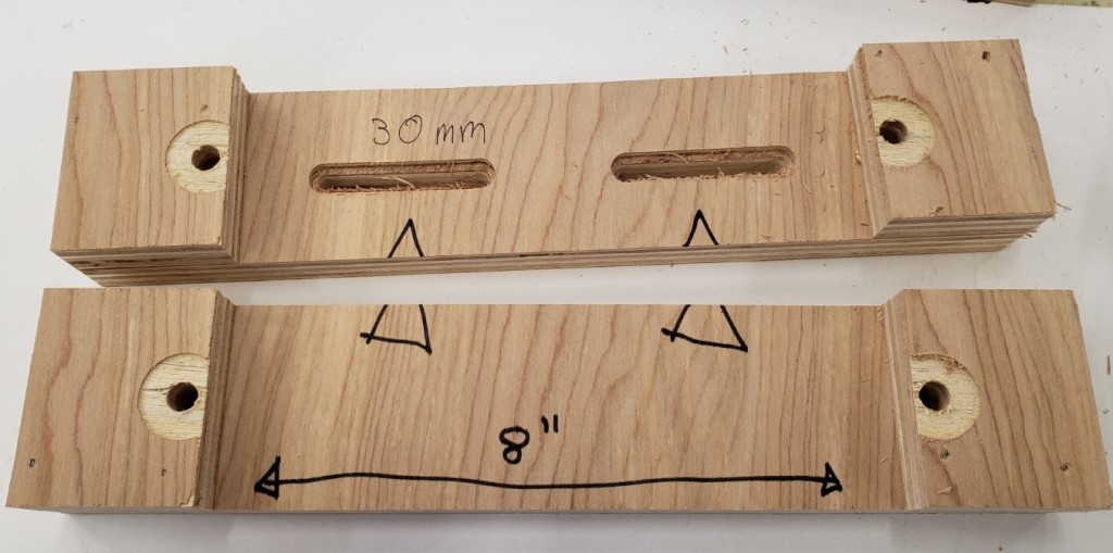
With the milling done, I cut it in half at the table saw, then added some alignment notes. Any 8″ wide piece of 3/4″ plywood or MDF should clamp in there.
To hold the sacrificial waste blocks I screwed in an M6 threaded insert to the bottom of the jig. Button head screws and fender washers sit in the counterbore and clamp down the waste boards.
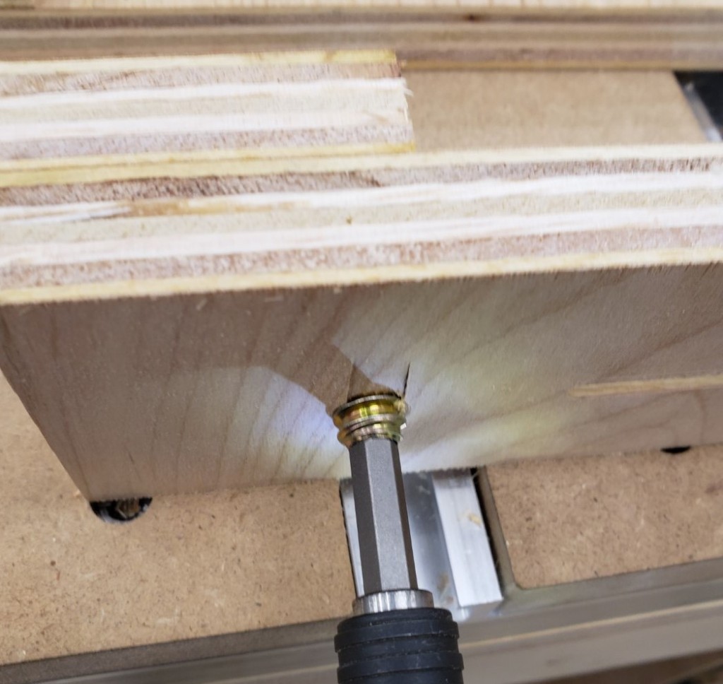
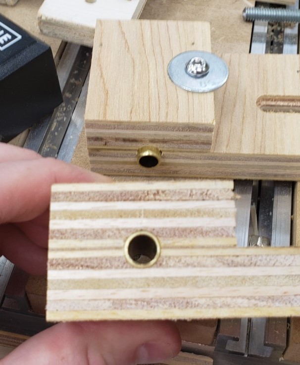
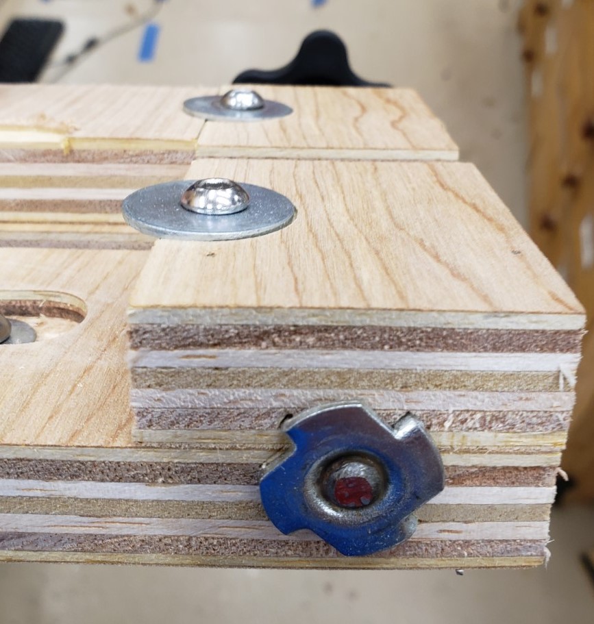
I clamped the boards together and drilled all the way through with a 3/8″ bit. It gave clearance for a 5/16″ t-bolt hammered into the back, and brass tubing in the remaining spaces. This acts as a bushing for the 5/16″ bolt. I used thread locker to keep it secure in the back, then large knobs in the front to clamp everything down.
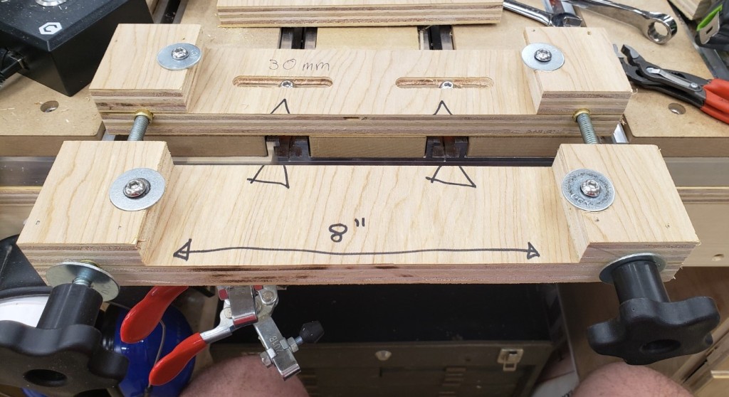
Here it is fully installed without the waste boards inserted yet. You should be able to get at least 2 uses out of a 3″ wide waste board by flipping it around after the first cut pattern. I found mine were in good shape even after making 16 cuts of the finger joint pattern.
This version doesn’t need the cam clamps, the vise like action of the two threaded screws has plenty of clamping power. Similarly, I didn’t need a height stop. I could very accurately feel when the board was flush with the top of the jig. The second round of drawers went very smoothly with this jig!
