Many moons ago I had a shapeoko 2 cnc router/mill, and loved it. The tool chain was horrible, but it was my first CNC device. I created all sorts of things with it until I got my 3D printer. My attention was diverted due to printing’s ease of use and versatility. Eventually I forgot all the feeds and speeds and tricks for using my shapeoko. The learning curve was steep and I never got around to it. It got sold when I found out we were having a kid. Fast forward 2 years later and I stumbled into where CAM and mill control was in the modern era. Things have improved a lot in the 8 years since I first picked up a mill.


This is a 3018. Stock the way I got it. There are many versions out there, and this one is the prover from sainsmart. It was a good deal around christmas, so I broke down and got one. Out of the box it does a decent job, but there are a few issues. There are limit switches you can install, but they reduce the travel by an inch in either direction. Pretty bad when the thing moves less than 7×11″ in the first place. It could use lighting, and their touch probe is way too thick. I’ll fix it.
Y Limit Switch
I’ll start with the Y limit switch. Y is front to back if you are looking at the device. Underneath, there were tapped spots for you to put the limit switch. It hits up against the bearing blocks to trigger the machine to stop. With those installed you get a lot less travel.


Instead I found some tapped holes that are off to the side but unused. I printed a bracket to hold the switches out of the way of the bearing blocks.
With that installed I printed a stop block that would activate the switch. The base plate is 30×30 aluminum extrusion, so an appropriate T-nut let me fix the block in place. I have it set to stop the stage right before the bearing blocks hit. I could have milled the switch mount and stop block, but am much faster with 3D printing right now.


X Limit Switch
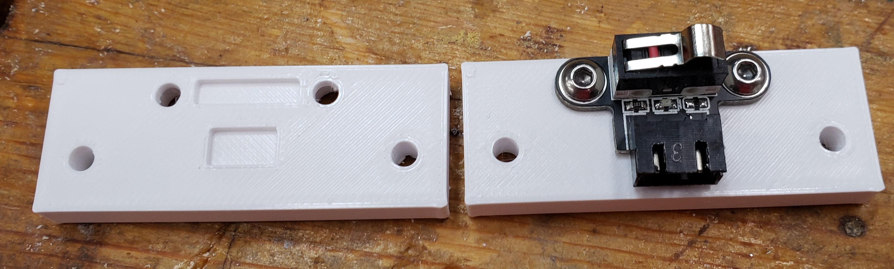
The Y limit was pretty easy, the X limit is going to be more invasive. Again, the position they want reduces left and right travel. I printed a tight spacer to keep the contacts off the aluminum side wall. I want the switch at the same height, but moved towards the back of the machine. I’ll drill and tap the side walls to mount my switches. I have to do it from the outside because I can’t get tools in around the extrusion and lead screws. Here is a switch temporarily installed with one screw on the outside.


I drilled and tapped the first hole, installed the switch, used a center transfer punch to mark the second hole’s location, then drilled and tapped that.


To make a stop block I drilled and tapped the back of the X carriage and installed another 3D printed block. The Z stops came pre-installed, and I didn’t see any way to modify them that would get me more travel. They let the stage use almost all of its small travel. My last mill never had limit switches. Now I can automatically home the machine each time and drive around without fear of impacting an end.


Lighting
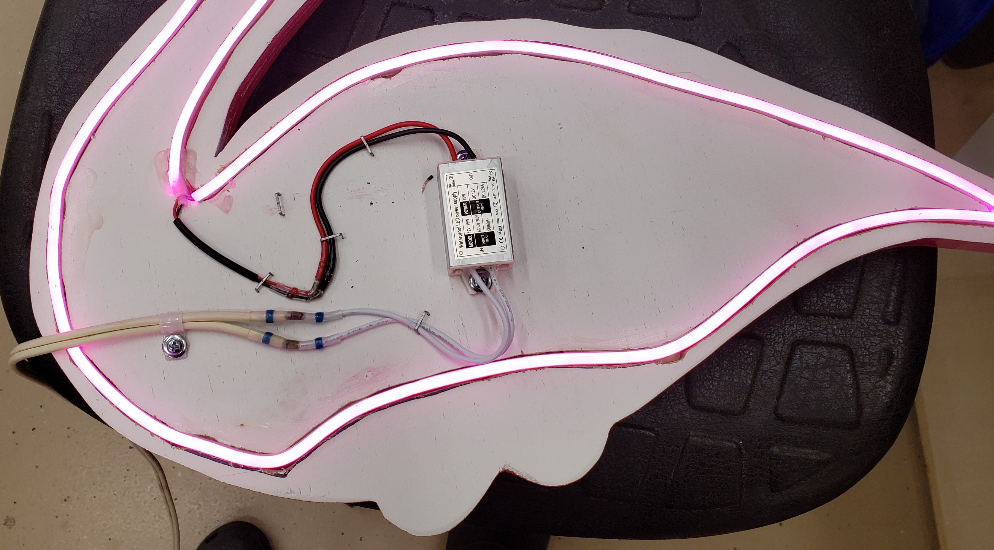
All good devices need a bit of disco lighting. Or at least something to tell you when the power is on. Power and USB are different, so you can be chatting with the USB, but having nothing move because the power is off. To remedy this, I soldered some leads onto the 24V input power switch. A buck converter dropped that to 12V to run my LED strips. The wiring is getting mess, but I just bonded the buck down to the outside of the electronics cover. It got its own little 3D printed cover (not shown).


I used 20×20 twist in t-nuts to mount the c-clips that came with my LED strip housings.


Here is the tool with the lights off and on. It kind of blows out the camera, but the extra lighting is really helpful to work with in person.


New Touch Plate
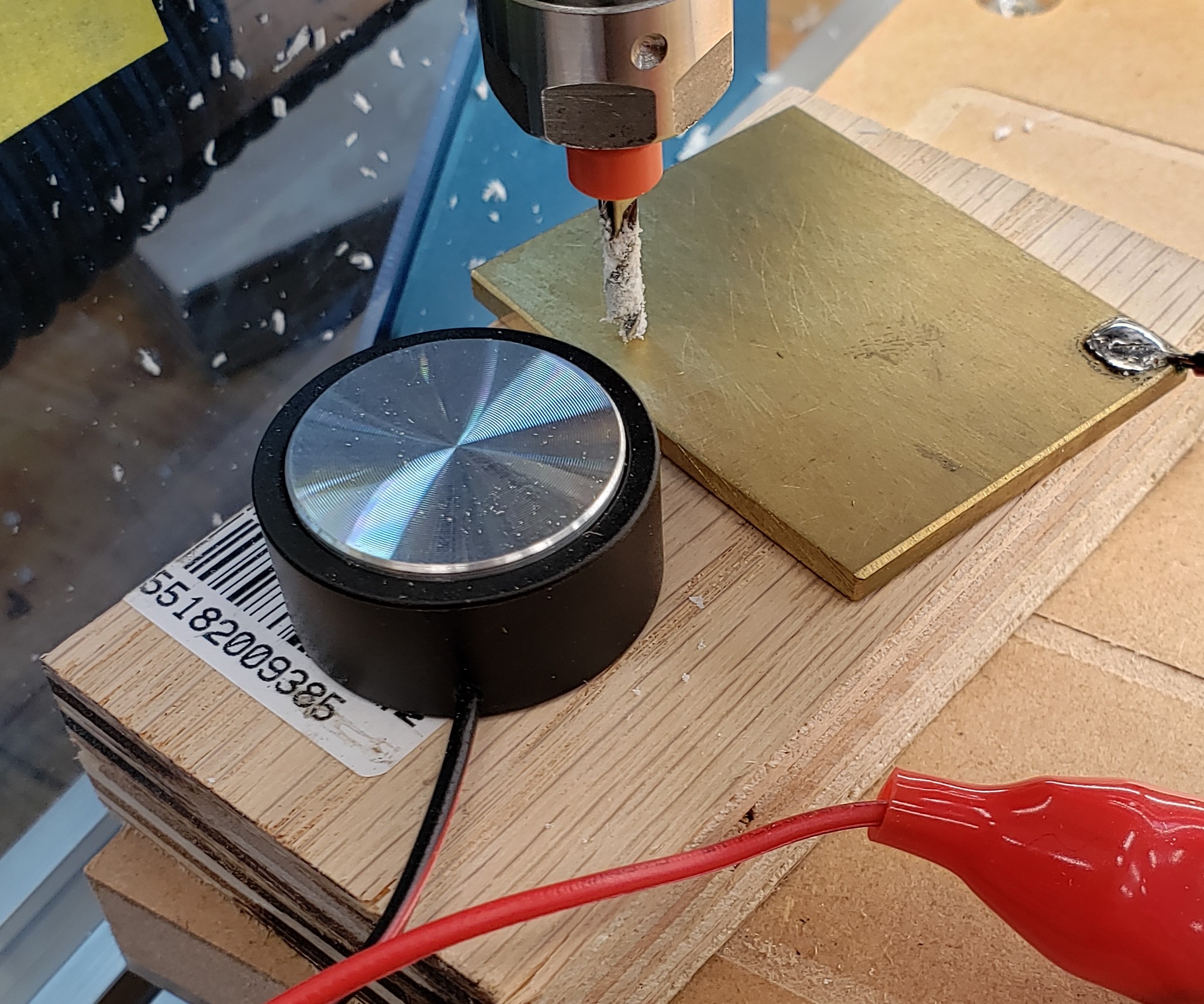
Last but not least, I made a new touch plate. The one it came with is pretty darn tall and you have to clip the positive lead to the router bit. Mine is 1/8″ brass, and I soldered the other side of the lead onto the motor housing. I don’t have the Z-travel to use their touch plate in most situations, while mine always slides in.
To keep it close and handy I milled a little holder out of some PVC material I had. I could have printed this, but it was a good mill exercise to get used to fusion 360. I have a long ways to go, and spend a lot more time on the CAM to cut this shape than I would on the slicer settings to print it. Now I can accurately find the Z distance between my bit and work piece. This is a big helper that my last mill never had.