CNC Joinery Jig

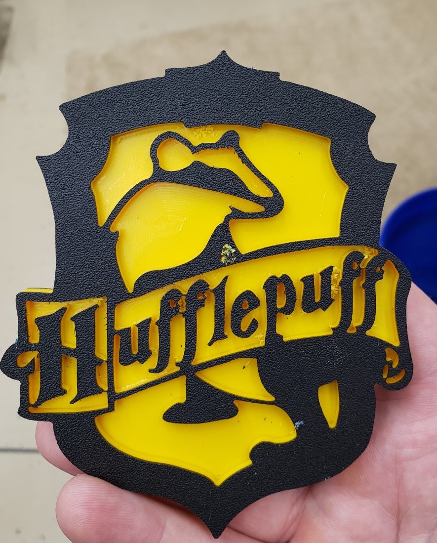
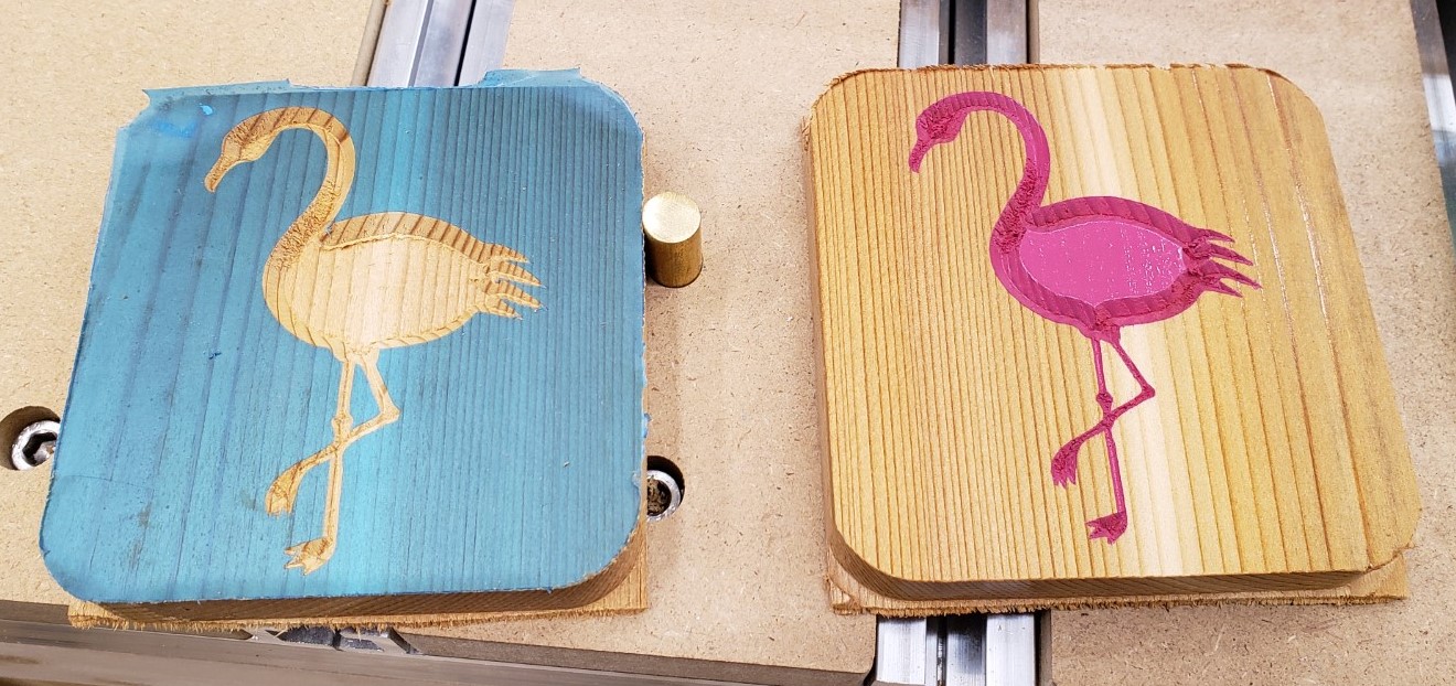
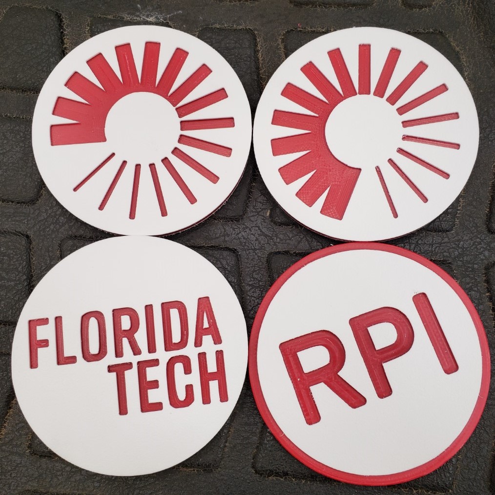
Updates have been few and far between recently. Being a toddler parent doesn’t afford me a lot of time in the shop, and the learning curve has been steep on the mill. That said, I have gotten a lot craftier with it and have fusion 360’s complicated CAM system pretty well whipped. I built a set of drawers for my mill and in the process created multiple versions of a joinery jig, and even dove into python code to post process my g-code. It will take a few posts to unravel it all. First up, a few shots of random fun coasters I made the past few months.
The Drawers

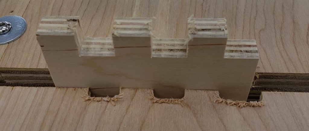
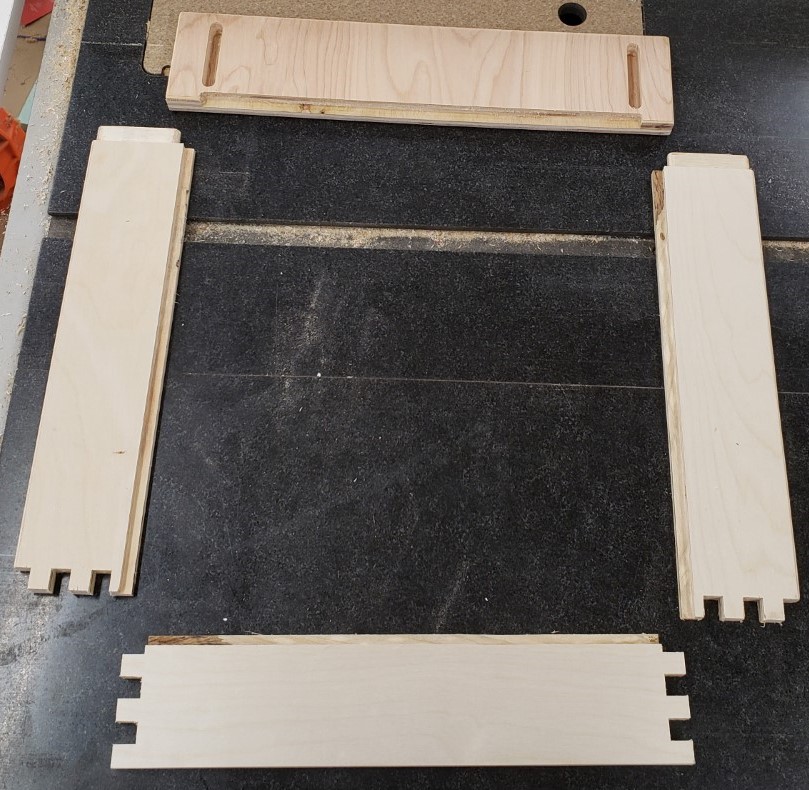
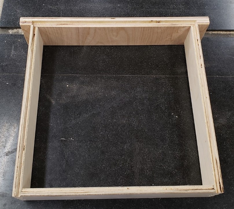
What kind of drawers are we talking here? Nothing too fancy, but I wanted the ability to make finger joints without too much fuss and setup. I’ll leave the details of the joinery and lessons learned for another post. For now, this one has finger joints on the back, and a tenon into the drawer front for the sides. Hidden and very strong.
Jig V1

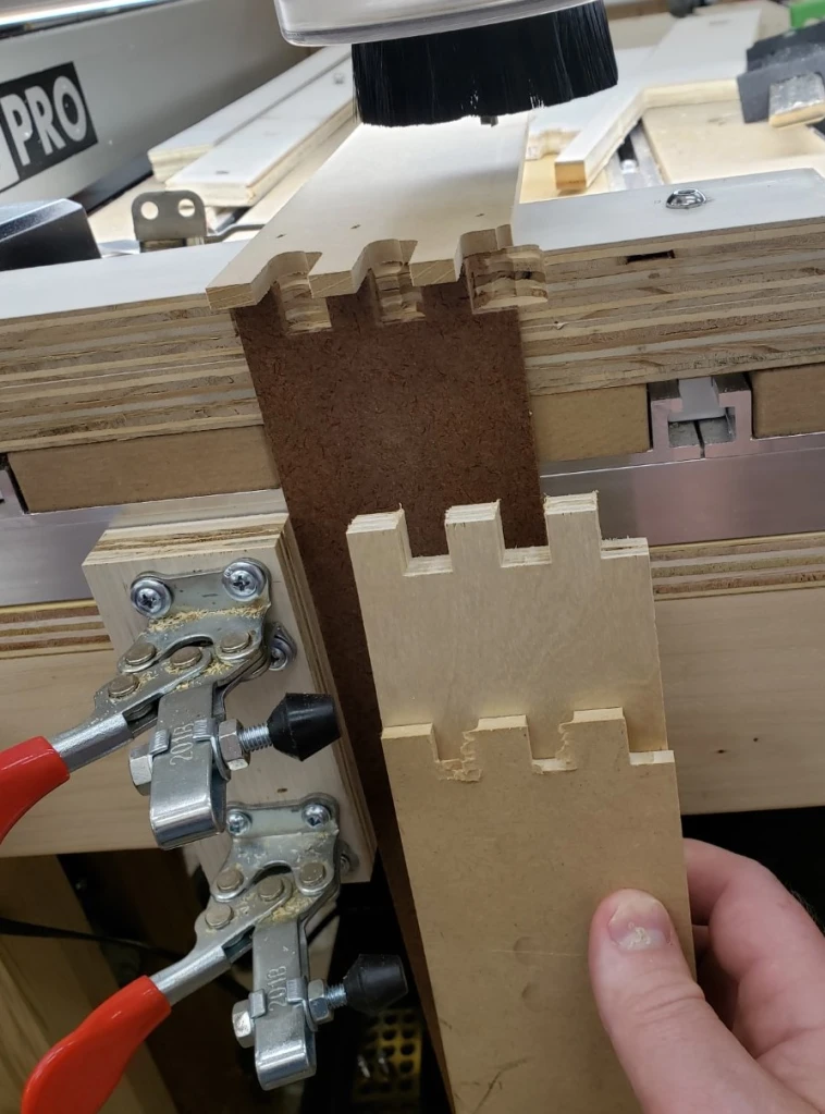
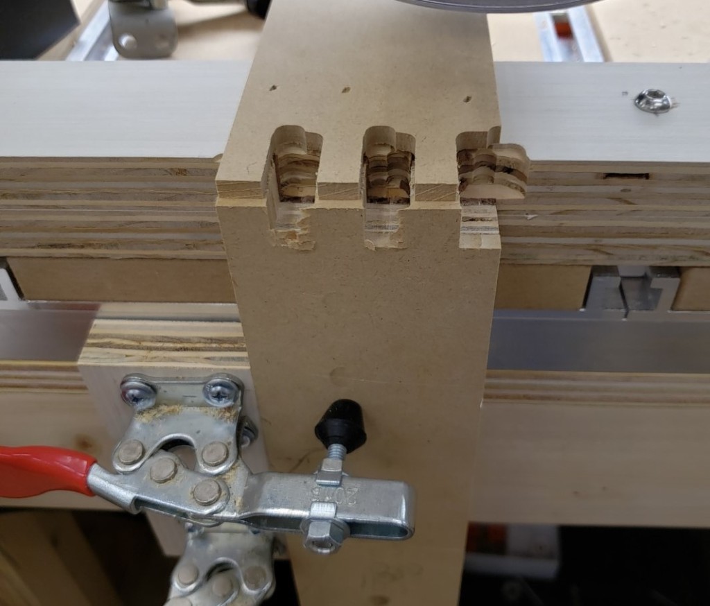
The first jig was a pretty simple setup. I attached a piece of plywood to the front of the mill table to align boards vertically to the table. It was square to the top and had cam lock clamps to hold the board in place. Sticky backed sandpaper provided secure grip on the table side and on a clamp board. I had a double layer of plywood screwed down to the table behind the board to back the cut and a plank of 1/4″ MDF on the font. This gave both sides of the cut support to prevent blowing out any drawer side pieces.
Clamped side in place

With this setup you could repeatably clamp a board in place and usually get a pretty good cut without too much fuss. Replacing the backer was a huge pain, and the top stop was only good for one shape. It worked for my first 3 drawers, but after that I stopped to think of something better.

Joinery Jig V2

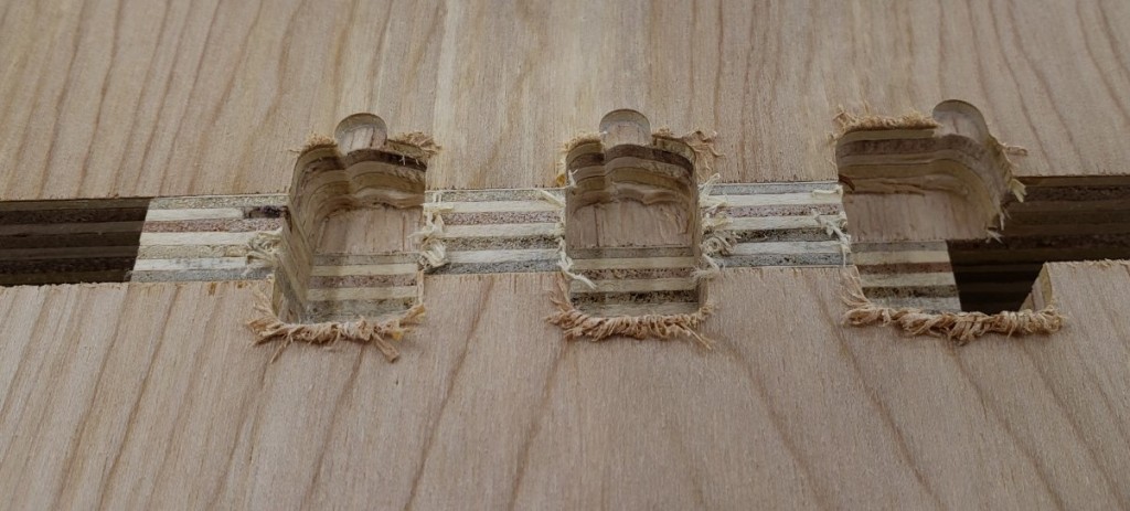
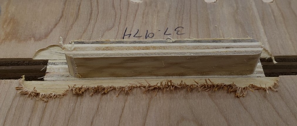
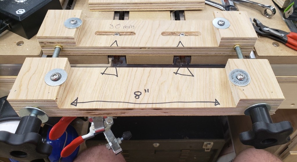
The next version has a two half system. The back half bolts down to the table top while the front half slides and clamps the board to be processed. There are sacrificial inserts that back all of the cuts to prevent blow out. Those are held in place by two clamp bolts on either side.
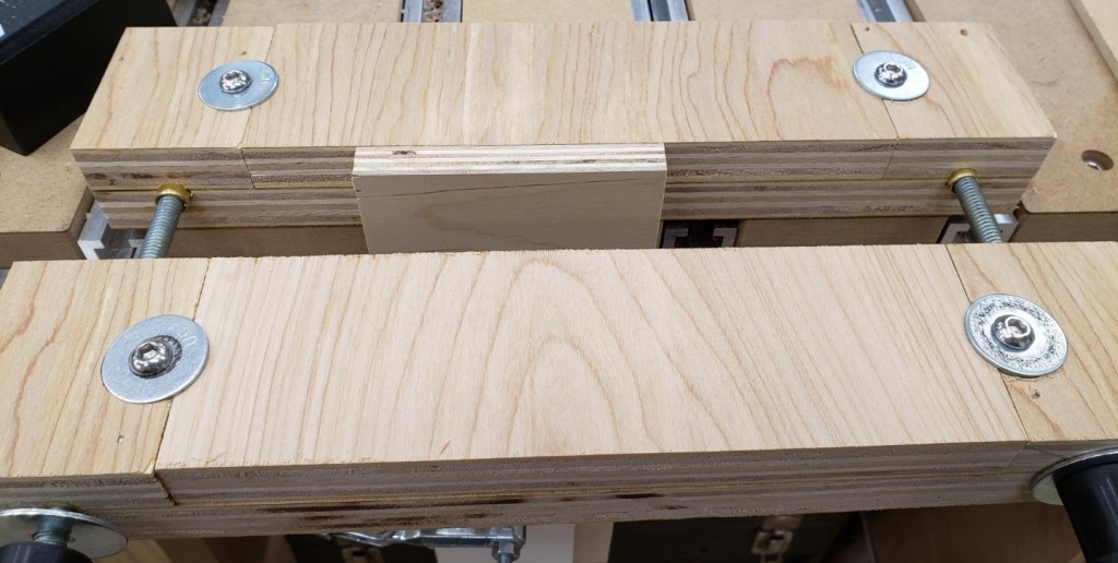
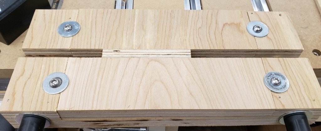
To create the jig I attached two pieces of 34″ plywood to the outside edges of a larger piece of plywood with glue and nails. This would be the base area for the rails/bolts that clamp the two halves together. I will mill it all as one piece and cut it in half at the table saw.
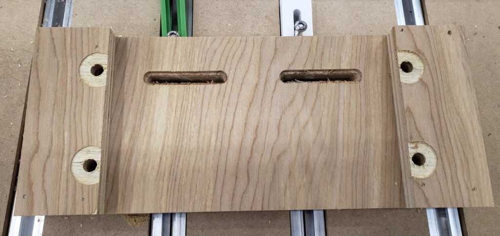
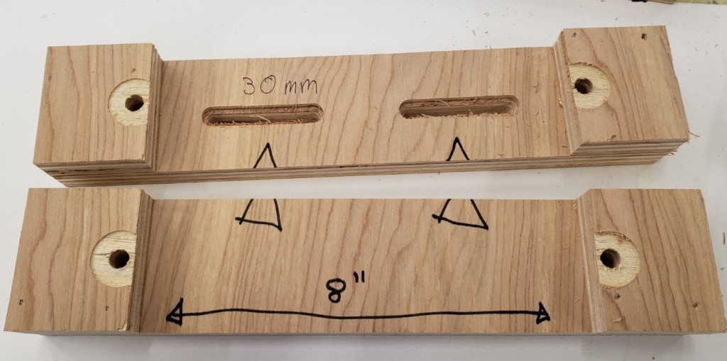
The slots are 50mm long and spaced 100mm apart. That should let me position it anywhere on my table top by always spanning two rails. I started with them just wide enough to hold the bolt head, but eventually widened them to allow washers. Bare screw heads on plywood would eventually compress and allow the jig to rotate.
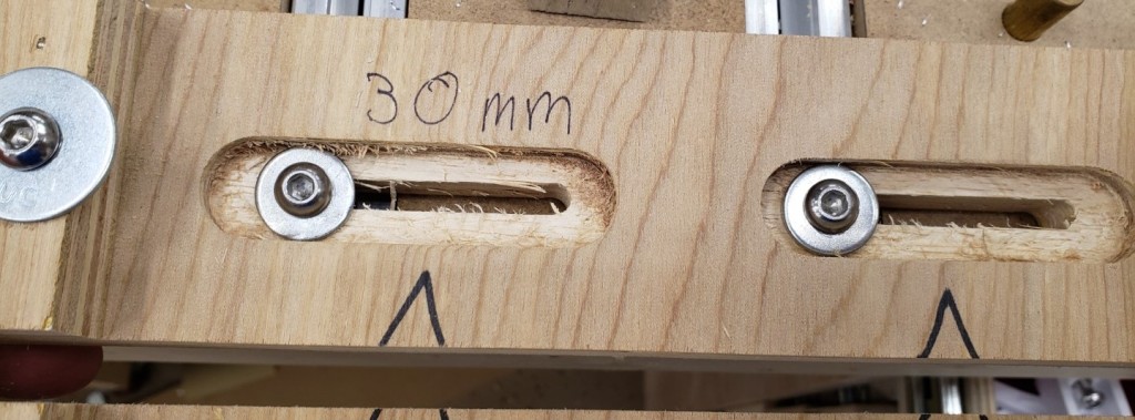
Widened to allow washers

With the milling done, I cut it in half at the table saw, then added some alignment notes. Any 8″ wide piece of 3/4″ plywood or MDF should clamp in there.
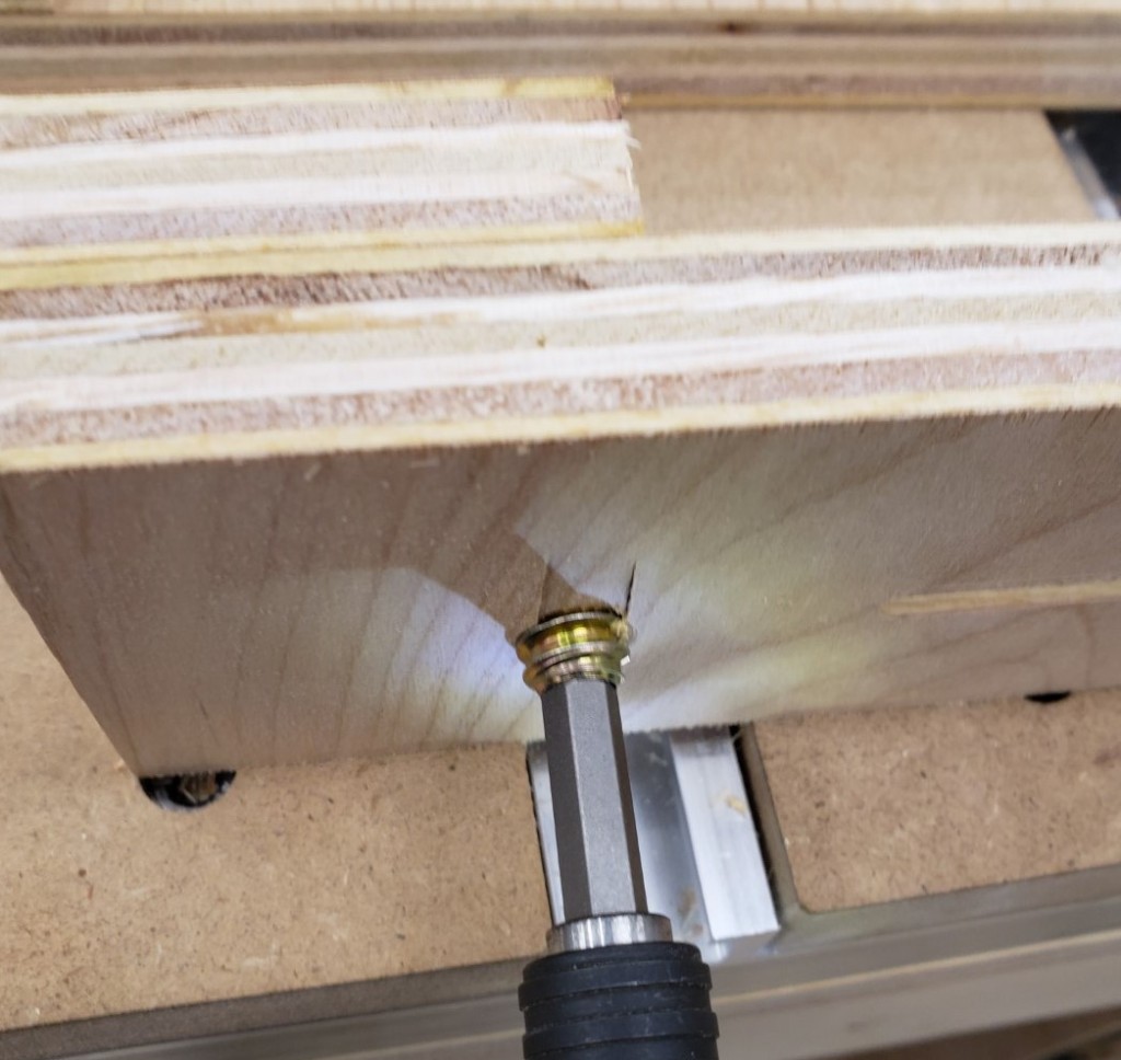
To hold the sacrificial waste blocks I screwed in an M6 threaded insert to the bottom of the jig. Button head screws and fender washers sit in the counterbore and clamp down the waste boards.
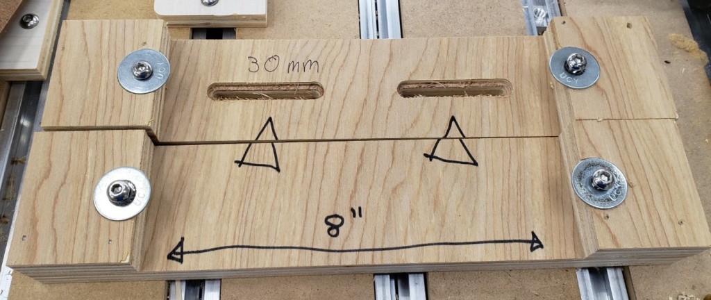
I clamped the boards together and drilled all the way through with a 3/8″ bit. It gave clearance for a 5/16″ t-bolt hammered into the back, and brass tubing in the remaining spaces. This acts as a bushing for the 5/16″ bolt. I used thread locker to keep it secure in the back, then large knobs in the front to clamp everything down.
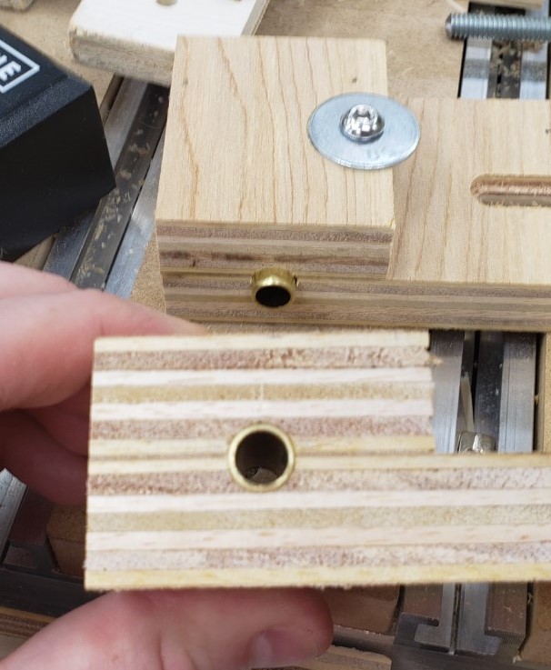
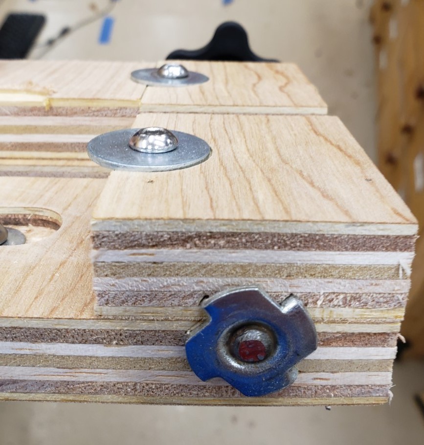
T-nut secures 5/16″ threaded rod

Here it is fully installed without the waste boards inserted yet. You should be able to get at least 2 uses out of a 3″ wide waste board by flipping it around after the first cut pattern. I found mine were in good shape even after making 16 cuts of the finger joint pattern.

This version doesn’t need the cam clamps, the vise like action of the two threaded screws has plenty of clamping power. Similarly, I didn’t need a height stop. I could very accurately feel when the board was flush with the top of the jig. The second round of drawers went very smoothly with this jig!

Disk Sander Circle Jig

My Bandsaw Circle Jig actually started out as an idea for a disk sander jig I saw in one of my woodworking magazines. They used a sliding arm with a screw adjuster to fine tune the diameter of the circle. I thought this was neat and it slowly evolved into the arm I made for my bandsaw jig.

I already had an arm with T-slot track in it from the bandsaw project, so I figured that would get used in both jigs. You could cut on the bandsaw, then fine tune on the disk sander. The construction method I used before applies well here too. 3D print a runner to go in the miter slot, start with a base of 1/4″ MDF, then attach 3/4″ MDF on top to guide the sliding arm. I CA glued the runner in place with it all aligned, and then screwed it in from underneath.

I don’t have any features to keep the adjustment arm locked down because the disk sander’s movement should push the work piece into the table and keep it stable. Hopefully that theory continues to work out for me.


The new thing here is the adjuster. The wood magazine had something with a T-nut and bolt. It was fine, but I figured a printer could do better. The knobs were something I had designed earlier. Each holds a 1/4″-20 coupling nut. The adjustment screw is a bit of threaded rod with a coupling nut bonded to one side. The other was rounded via a drill and bench grinder. The knob will glue on to the nut and the rounded end will push up against a hard stop. Having it rounded should mean there is only point contact and will make for smoother more even adjustment.

The adjuster uses a bolt in the t-track of the adjustment arm to clamp itself down in the rough position. I added a block to the bottom of the jig and bonded a big fender washer down for the head of the adjustment screw to contact. It should be a very firm stop and won’t wear easily.

Putting it all together, and with a few coats of polyurethane to keep the MDF stable, I tested it with another sharpening wheel. My last one was a little small, so I made a new bigger thicker one. The only thing to note is that doing heavy sanding in one spot will load up the paper badly. Sliding down the table occasionally will help even out the wear.

Bandsaw Circle Jig

I have a router circle cutting jig from milescraft that works pretty well. It screws down a center and uses your router on an adjustable arm to make big circles. It does take a bit of setup though, and anything under about a foot in diameter is pretty awkward. There are loads of bandsaw jig ideas, so why not add mine to the pile? I think I have three things that are slightly unique in this design. Not revolutionary, but a bit different.

1. I started with a 3D printed miter slot runner. It is T shaped so once you slide it in the jig can’t come up off the table. Most folks make wood runners. Those are fine, but with printing it is a lot easier to dial in a T-slot so that the jig can’t lift. It comes with countersinks for #6 mounting screws.

2. The jig needs some kind of sliding arm to hold the piece being circle cut and set the circle radius. Dovetail slots and all sorts of things are employed. I took a T-track and glued it into a piece of 3/4″ MDF. Even 1/2″ screws would have been too long, so I just used epoxy. It holds well. A look from underneath shows that a bolt and knob let you lock down the circle radius arm in position.

3. To hold the work piece, most jigs use a small nail sticking up from the adjuster arm. You would drill a small hole in the part and pin it on the nail in the jig. Instead, I wanted a more flexible solution. I cut a 1-1/4″ hold in the end of my adjustment arm so I could put in 3D printed holders. One is 1/2″ in diameter so I can cut a MDF circle for my buffer. The other has a countersunk hole so I can screw a small #6 screw into the work piece. Optionally, there is enough space there to double sticky tape the puck down and use the center hole for alignment. I can print all sorts of posts or pins to suit my cutting needs.

To put that all together, a piece of 1/4″ MDF was CA glued to the runner (temporary) and pushed into the saw till it reached the middle of the jig. I glued a little stop in front so it would hit the bandsaw bed and stop in the same place every time. I then glued on 3/4″ MDF around the centered adjustment arm. That gave me enough material to screw on, from underneath, the glued runner. That all got pushed in again to the saw to cut through the new 3/4″ MDF.

I did some measuring, marked our the rough radius locations, and coated everything in a few coats of thinned polyurethane. It struggles a bit with anything under a few inches in radius, but a different blade would help. Up to 2 foot circles are possible. Above that and I will go to the router jig. To try it out, I made a sharpening wheel for my buffer out of 3/4″ MDF.

  1. Set the runner to the appropriate radius and lock the knob
  2. Install the square of material to be cut on the peg
  3. Push into the saw until you hit the stop
  4. Slowly rotate all the way through the circle
  5. Done!

Folding Helping Tower

A helping tower is like a step stool you use in the kitchen with a child. It gets them up to a height to be able to help out with basic cooking tasks. Unlike a basic step stool, this has sides and a back so they can be kept in place, and not easily fall off. There are a million different examples online, but most all of them are bulky (by necessity) and end up being a bit of an albatross in the kitchen. I wanted a folding one that could be packed away easily. It took a lot of prototyping, but I did it.

I normally jump into projects, but this one was a very slow methodical trial and error build over nearly 2 months. A broken AC and baby tasks stretched that out a bit. The front frame of the device consists of two permanent uprights with an upper and lower stretcher. To those uprights, a set of folding sides are attached. The right upright is thinner so that the two fold over each other in an overlapping pattern.

The middle stretcher will hold the step and let it swing into place. I needed a strong stop that would support the step and draw the sides into the step. I used a dovetail bit on the bottom of the step to make a slightly angled groove. The stops had the same angle in reverse. Now, the more weight put on the step, the tighter it will draw the sides in.

The seat can fold up and the sides fold in. Everything is compact and easy to deploy. The stops are only 1/2″ thick and don’t interfere with the fold up.

It needed some kind of back to keep people from falling off backwards. A simple swing arm accomplished this task. It was narrow enough so as not to interfere with the unit’s ability to pack up. This had all the rough mechanics I wanted, but was narrower and not as deep as I felt it should be. Also I wanted the step portion to be adjustable as the child grows. On to the next prototypes.


I am going to use dowel nuts and binding screws to make something that was strong, but could be removed and reassembled. It would take a number of holes drilled in the right places to make that work. I planned the sizes of the parts and printed out drill guides that would hold brass tubes to act as drill bushings. The brass won’t last forever, but is easy to cut and insert, and helps keep the hand drilling accurate.

First up I clamped the jig in place and used a transfer punch to mark the centers of where the barrel nuts will go. This makes drilling on the drill press easy.

Next to accommodate the bolts, I need to drill a long hole end-on to meetup with the cross holes. This can’t vary much and the parts are too long to use the drill press, thus the drill jig idea.

With both sets of holes accurately drilled, the nuts and bolts will meet up in the correct spots.


With the folding and adjusting mechanics worked out I could move on to the real thing. I selected 1×3 pine for the uprights and spreaders. The step spreader got its holes drilled with the above jigs, and the other two spreaders received a set of fair curves thanks to my new drawing bows.

Part of the assembly folding out and being stable is having the sides only fold out 90 degrees. They must positively stop when they reach the right angle. I do this by firmly clamping the sides and uprights together and routing a small pocket for the hinges. This 3d print has a center-line mark on it and is perfectly spaced to make a tight mortise for the hinges. The result is a flush hinge and sides that do not swing out past where you need them.

I assembled the step and determined how high it could go when folded up. Too high and the step hits the top spreader. Marking those places I could make a row of holes that would allow the step assembly to adjust as needed. The sides and uprights got a set of holes placed every 2 inches.

To lighten the structure and add something fun, I printed a series of shape templates. Double sticky tape holds them down, and a plunge router cuts them out quickly. I made 8 unique shapes and it really adds a lot.

I put the center spreader in at the top most position and marked where the stops should be. Each one has two t-nuts hammered in place. Bolts go in from the outside to hold those securely. Now to adjust the height you have 8 bolts to remove. 4 from the stops, and 4 from the folding step. The final unit is light, compact when folded, looks decent (even though most of it is plywood), and should have enough room for any kid small enough to need it. The swinging back stop is made with another set of dowel nuts and binding screws. Everything got a coat of shellac as basic protection.

As a final bonus, I was able to cut the shapes out carefully enough that they all survived in tact. I rounded the edges and shellacked them as well.

I want to be able to re-create this again in the future. Here is a rough parts list with sizes. Dowel nuts and binding screws are both 1/4-20s.

QtyDescription
6Dowel Nut
4Binding Screw, 5/8”
6Binding Screw 1-3/16”
4T Nut
8Pan head screw, 1-1/2”


1Back Bar: 18-1/4 x 1-1/2”
3Spreaders: 16 x 2-1/2”
1Upright Left: 38 x 2-1/2”
1Upright Right: 38 x 1-3/4”
1Side Left: 36 x 10”
1Side Right: 36 x 10-3/4”
1Step: 16 x 11-1/2”

April 2019 Prints

RTIC Tumbler Handle

For some reason RTIC has changed the shape of their 30oz tumbler. Not sure if YETI did this, and they followed suit or what. I suspect it is a plot to sell more handles and accessories. As it stands, the old handle I designed doesn’t fit on the new style of cup any more. The taper angle and diameters are just a little different.

My old handle was printed in 2 parts because most low end printers (including the one I owned at the time) couldn’t print something that big. Now a days at least a 6×6 bed size is pretty bog standard. This new design will be all one piece. The cup is large enough in diameter that getting my calipers on it wasn’t going to work. I printed some rings of different diameters and used them to estimate the taper angle of the new cup.

With that figured out I just printed a new handle that looks a lot like the old one, only with slightly more finger room and a longer grip. Thingiverse link

Drawer Pull Centering Jig

I picked up a Kreg cabinet handle jig for one of my recent projects, and because handles are something you install pretty frequently. It is certainly possible to do them well without a jig, but that always makes repetitive work easier. The jig does a good job of setting the height and width of the holes. It doesn’t center them on the drawer though. I made a few add ons to help with that.

I took a length Kreg track that you would normally imbed into a table to make moveable hold downs. Instead, this becomes part of the top fence used to set depth. Now with a spacer it registers across the whole top edge of the drawer. That also lets you use an edge stop. Now it is all centered. Once set you can put handles in the same drawer position over and over again with no more measurements or adjustments. The only downside is that there was a scale on the back of the jig for setting depth. That no longer measures true because this vertical stop doesn’t register where the old one did.

Router bits

Storage and organization is a place where the printer continues to be endlessly helpful. I have had this nice router bit set for years, but always had trouble getting the bits back in their slot. They end up clanking around the drawer and taking up more space than they should. A simple printed tray gives them each a home and takes up a lot less drawer space. For smaller prints like this, a label maker works better than trying to 3D print the text.

More Dust Collection Adapters

Woodworking Dust Collection Rule 1: No two dust collection ports are ever the same size… EVER

Once again I find myself trying to fit a dust collection hose on to some of my tools and wind up having to 3D print a custom solution. Why is it always like this? This time it is a port for my random orbit sander to 1.25″ hose (which isn’t really 1.25″), one for my belt sander, and an adapter to go from that hose to my dust deputy inlet (which has some funky taper on it). The good news is that the ridges left over from 3D printing these always helps the adapter stay in place, even if it isn’t perfect. This is exactly why industry standards and groups like ASME and SAE exist.

Vacuum Cart

I am trying to make a commitment to do better dust collection in the new shop. I want to prevent the thick layer of sawdust the was on everything in my last shop, and I want to keep my lungs healthy for another half century or so. I have a few projects coming up that are aimed at those goals. The first being a shop vacuum cart.

I have used a small shop vac for specific applications, but never had a general one to use at different places around the shop. My portable sanders, router, miter saw, and other dust generating tools often went un-vacuumed.

I picked out a decent sized vacuum that had good specs but wasn’t the highest end you could get. It seems like for another 100 bucks you got a few features and a marginal increase in performance. The next level above that would go to the pro-sumer version at 5x the price. Not gonna happen on my current budget. I took some of the old counter top material left over from the previous owner and routed a nice radius on the front.

I picked up the milescraft circle cutting jig for an upcoming project, but decided to give it a test run here. What a great jig! Well worth 40 bucks. There is going to be a 5 gallon bucket pre-separator before the main vacuum. I screwed a bucket to the base to hold the separator bucket and built up a platform to get the shop vac higher.

I did a lot of positioning and found that moving the bucket to the right side and rotating the vacuum to the left let the inlet hose clear more easily. I screwed the shop vac down through the base into the platform. Hopefully these screws don’t rip out. If they do I will lose a lot of vacuum pressure.

I got a dust deputy brand cyclone separator. It is supposed to spin the dust out to remove most of it before it gets to your filter. The hose port situation is a little awkward. The port up top goes to the shop vac. Even with elevating the vacuum it is an odd stretch. The hose wants to kink in on itself.

I took kind of a step back and had a think. This calls for some 3D printing. The top of the dust deputy has a tapered shape to it. I printed a matching ring that fits into a 2″ PVC elbow. The printed part got epoxied into the elbow and fits on the top of the dust deputy. The friction fit holds it well and makes a good seal, but lets it be removable.

With the elbow taken care of I created another fitting to push onto the end of the corrugated vacuum hose. This one works a bit like the fitting that comes with the vacuum. It slips over the outside and locks into the ridges. They are a 1/4″ pitch. I made a fitting with ramped one way rings inside. It pushes on easily, but is tough to remove. That should form a decent seal as well.

I might bond this part in eventually, but for now, the hose can be removed, and so can the elbow. It makes taking the bucket lid off and dumping the dust easier.

All assembled, I wanted to perform a test. I dumped out the main vacuum body and the removable bucket. I then went around and vacuumed a section of the shop floor around my miter saw and where I had been working on this project. I came up with a few cups of dust, a bunch of leaves and some chunks of stuff. The vacuum chamber was basically empty.

This is great news. Now I can easily empty the smaller bucket instead of the big vacuum. Instead of running a standard pleated filter I can use a bag. The bags get disposed of, but have a finer filtration level. With 99% of the junk getting caught in the vortex, the bags will last a long time. Plus, anything that might puncture a bag will get filtered out.

I have been using this a lot with my router for a really big dust job and everything has been working wonderfully. If you are thinking about adding a dust deputy to your shop vac, do it!

Corner Chamfer Router Template

I have gotten some good use out of my router radius templates. I saw an interchangeable jig system that did a similar job and included chamfers in addition to the radii. First a reminder of how they work. You sit the template on top of the wood and use a special router bit that is a cutter with a matched diameter bearing on top. The bearing follows the template and removes any wood that protrudes beyond it. Ideally you cut off as much waste as you can on the bandsaw or elsewhere. Routers don’t remove a lot of material well.

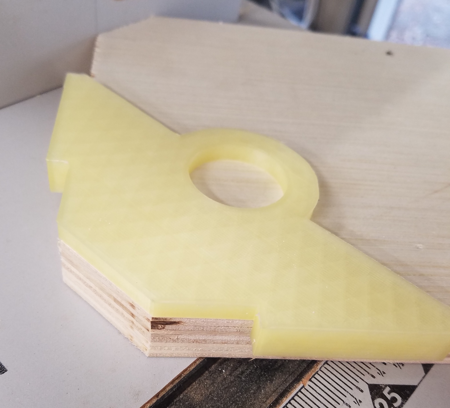
I modeled a variety of them from 0.5″ to 1.25″. The length given is a leg of the isosceles triangle that will get removed, not the hypotenuse. See the diagram below.

I printed a stack of them in case the need arises, and uploaded the design to thingiverse. If they look odd compared to my normal prints, it is because I used some cheap translucent filament I had lying around. I figure they will get torn up eventually, so no need to use the good stuff.

July 2018 3D Prints

Monitor Lift

One of my office monitors started making odd noises and showing crazy artifacts.  It got to the point of being un-usable, so I replaced it.  The pair was 5 years old and they don’t sell that model any more.  The cheap replacement I bought didn’t come in the same height and neither monitor had height adjustability.  A black circular disk printed at the right thickness matched the two screens up well.  A copious sprinkling of office desk clutter helps camouflage the printed lifter.

DSC_1420


Electrical Cutouts

There is going to be a lot of power and low voltage routing going on at the new house.  I have been practicing with my oscillating multi tool to get the cutouts just right.  A set of tracing templates would help.  It turns out low voltage and high voltage boxes are slightly different sizes.  Who knew?

They are pretty simple.  Color coded and labeled for their intended use, and thick enough to balance a bullet level on top.  Mark where you want the box to go, trace out the square, cut and install.


Laser Case

I picked up a laser range finder to help out with all the flooring and other work at the new house.  It is really amazingly accurate, but leaves something lacking.  There is no case.  The delicate output window for the laser is unprotected, and so is the screen.  A sock or super basic nylon case would have been helpful.  No worries, I printed my own, and shared it on Thingiverse.


Cup Holder

Our new place has a bigger yard and that requires a bigger mower.  I found a riding mower to act as my trusty yard steed.  It fulfills all of my boyhood fantasies of owning a riding mower except one.  The cup holder.  Basically it doesn’t hold my RTIC cup.  I fixed that with a little Husqy orange liner.  Can’t go losing your drink every time you hit a bump.

Death and Resurrection of a Drill Press

My beloved drill press is a Craftsman from the early 90s (I think) that I snagged on craigslist.  It has served me well, but is very difficult to move.  Top heavy and with a small base; even small shifts in position are precarious.  I am going to need to move it a lot soon, so when woot had a Bora Portamate mobile base on sale I snatched it up.  I was walking the drill press out of its corner to get the base installed when disaster struck.

20180720_135157

I tried to control it on the way down, but once it got going there was no stopping it.  I didn’t get hurt but the arm that holds the table broke off.  I still had a drill bit installed in the chuck, and that is what kept the table from sliding further.  It bent the drill bit, but the quill appears true.  I stood it up and started it spinning.  No wobble of any sort that I could see.  With that established I gathered up the broken parts.

Maybe a quick visit to the local welding shop would have me set right?  Apparently cast iron is very difficult to weld.  They were not wild about trying, and wouldn’t guarantee me any of their work.  Whelp…forget that.  After being really bummed for a day or two, I decided I could build up my own top table top out of the scraps I had around.  I gained enough confidence to install that mobile base.  It floats like a dream now!

DSC_1377

I started with a stout piece of oak drilled to match the table arm attachment point.  A drill press would have been really useful there, but I managed without.  From there I built out ribs that hold the top.  I made sure everything was square with respect to the drill bit before screwing them in completely.

The table top will be done with two layers.  The top will have a square cutout that holds a sacrificial drill insert, and the bottom has a hole so you can push up from the bottom to remove the insert.  I printed a square guide to let me cut out a 2.75×2.75 inch hole for the insert.  That new plunge router lets me do all sorts of cool things.

DSC_1402

I routed some slots for a set of aluminum t-slot guides that hold the fence in place.  The fence is just two pieces of the same plywood glued back to back.  I cut a dozen of the center inserts.  They all got an undercut chamfer to help keep dust from letting them sit level.  This table is smaller than my last, but I feel it is more functional by far.  It was a good recovery, and ultimately led me to making a better drill press table.

DSC_1407

DSC_1408