CNC Joinery Jig

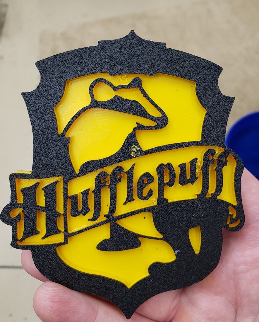
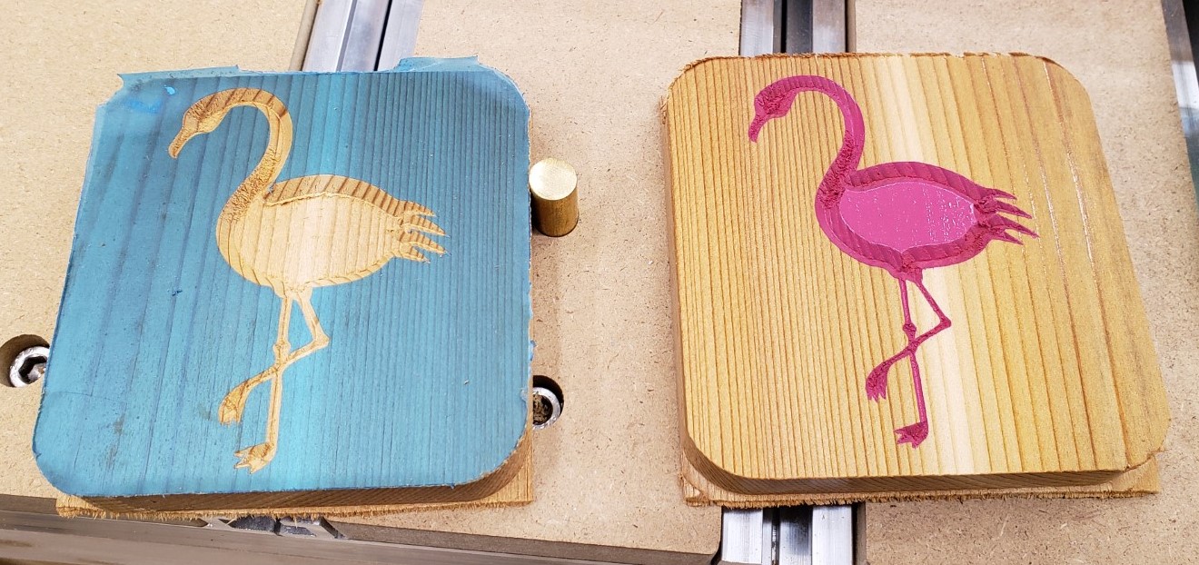
Updates have been few and far between recently. Being a toddler parent doesn’t afford me a lot of time in the shop, and the learning curve has been steep on the mill. That said, I have gotten a lot craftier with it and have fusion 360’s complicated CAM system pretty well whipped. I built a set of drawers for my mill and in the process created multiple versions of a joinery jig, and even dove into python code to post process my g-code. It will take a few posts to unravel it all. First up, a few shots of random fun coasters I made the past few months.

The Drawers

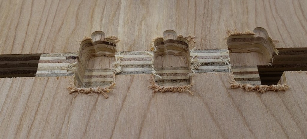
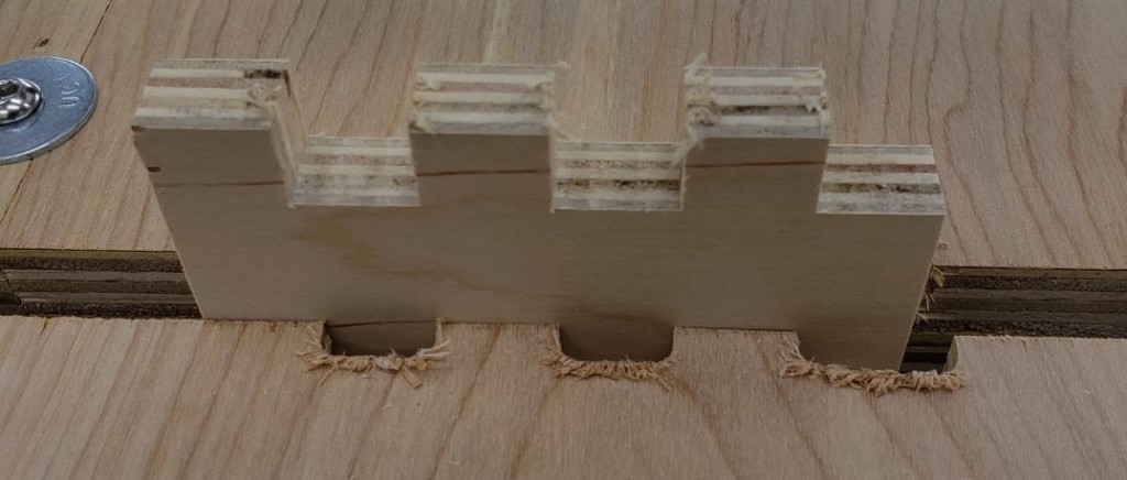
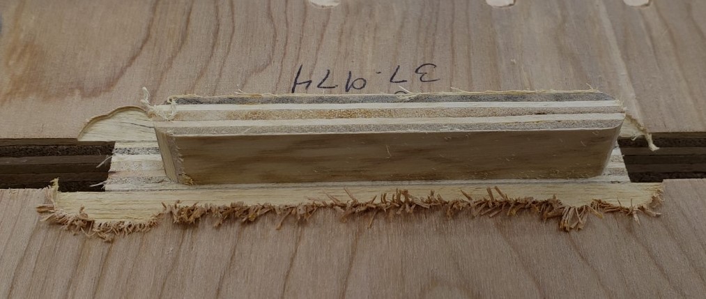
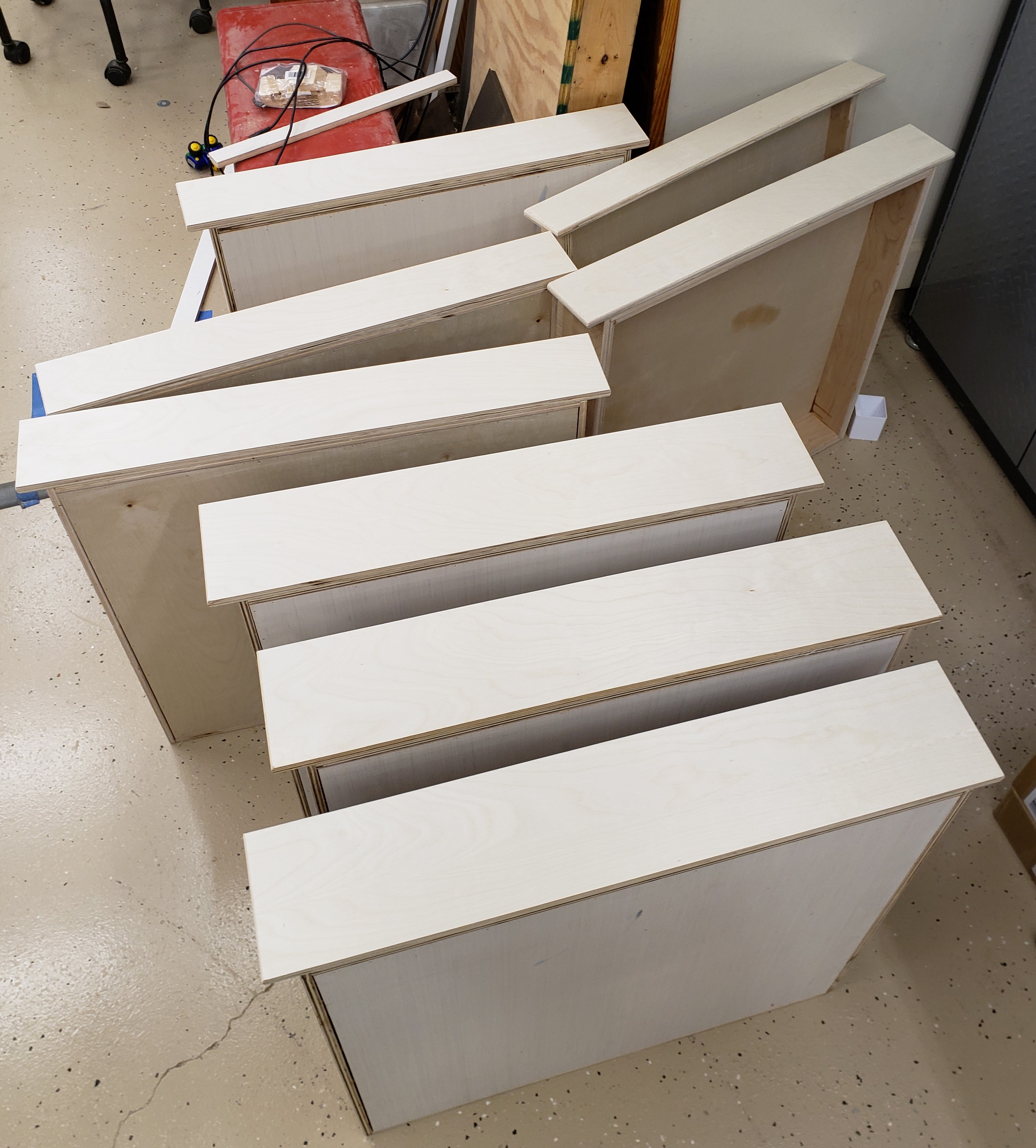
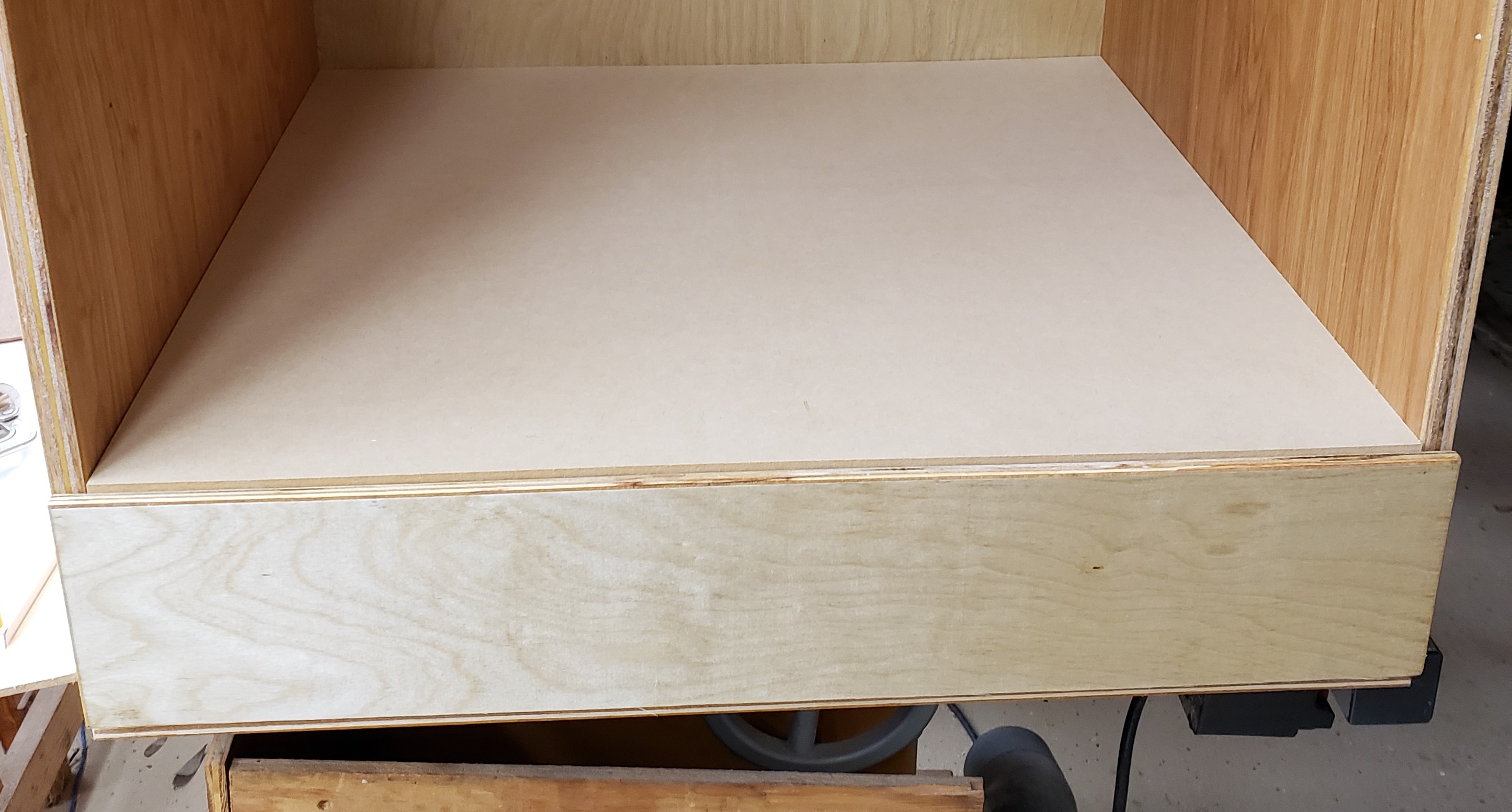
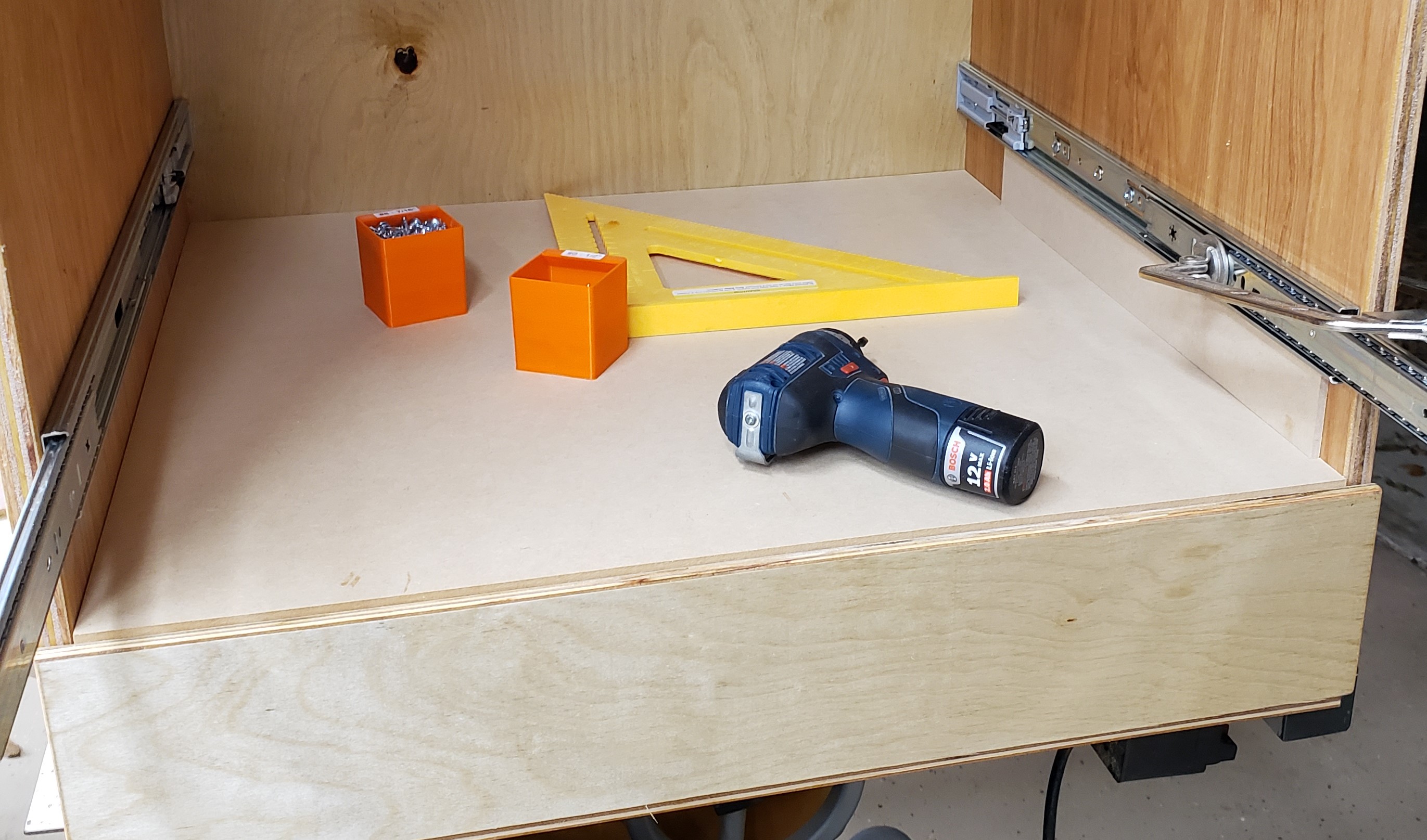
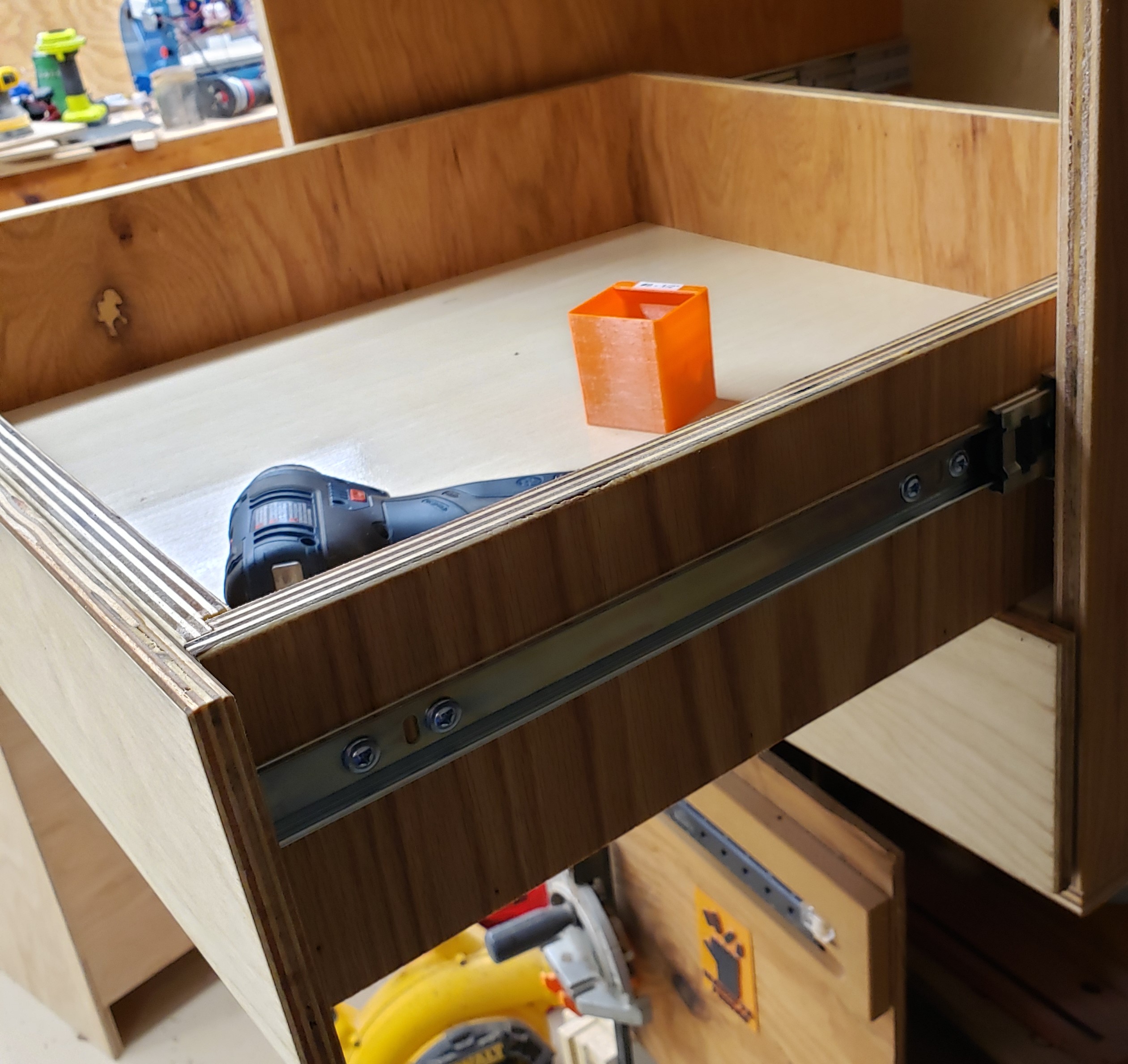
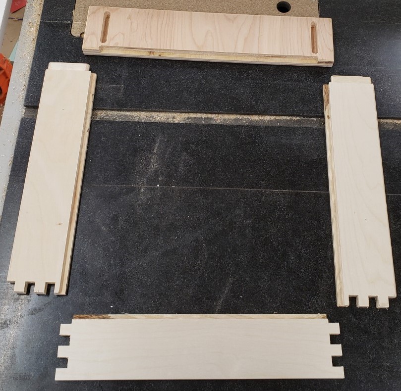
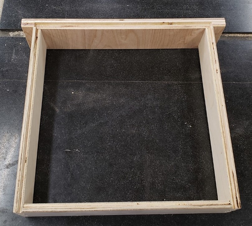
What kind of drawers are we talking here? Nothing too fancy, but I wanted the ability to make finger joints without too much fuss and setup. I’ll leave the details of the joinery and lessons learned for another post. For now, this one has finger joints on the back, and a tenon into the drawer front for the sides. Hidden and very strong.
Jig V1

The first jig was a pretty simple setup. I attached a piece of plywood to the front of the mill table to align boards vertically to the table. It was square to the top and had cam lock clamps to hold the board in place. Sticky backed sandpaper provided secure grip on the table side and on a clamp board. I had a double layer of plywood screwed down to the table behind the board to back the cut and a plank of 1/4″ MDF on the font. This gave both sides of the cut support to prevent blowing out any drawer side pieces.
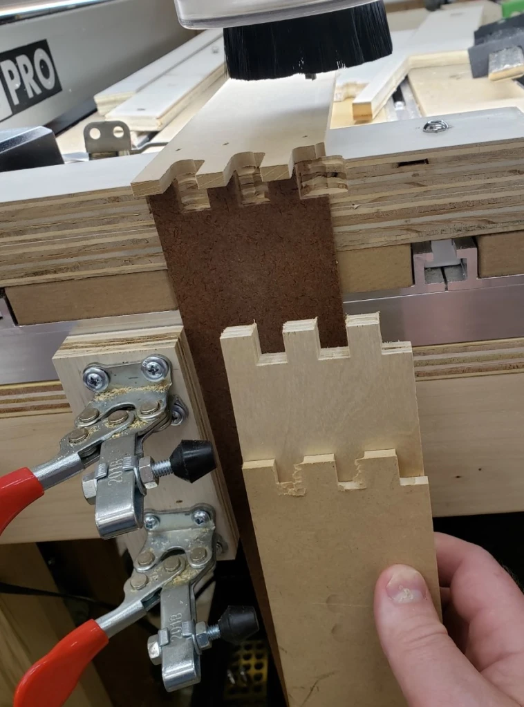
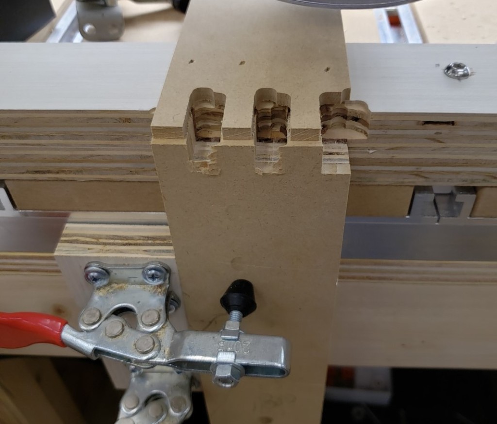
Clamped side in place

With this setup you could repeatably clamp a board in place and usually get a pretty good cut without too much fuss. Replacing the backer was a huge pain, and the top stop was only good for one shape. It worked for my first 3 drawers, but after that I stopped to think of something better.

Joinery Jig V2

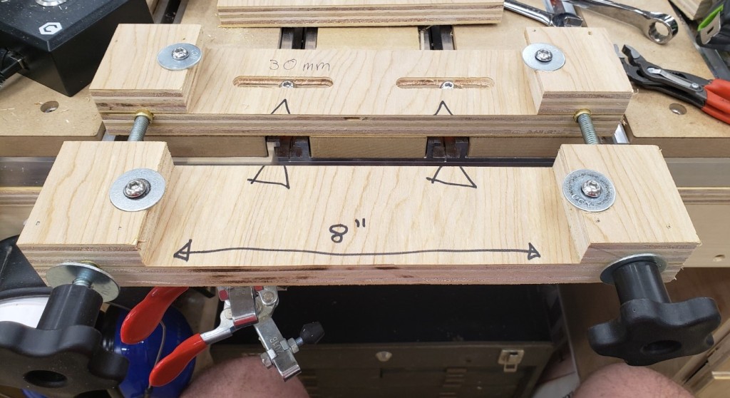
The next version has a two half system. The back half bolts down to the table top while the front half slides and clamps the board to be processed. There are sacrificial inserts that back all of the cuts to prevent blow out. Those are held in place by two clamp bolts on either side.
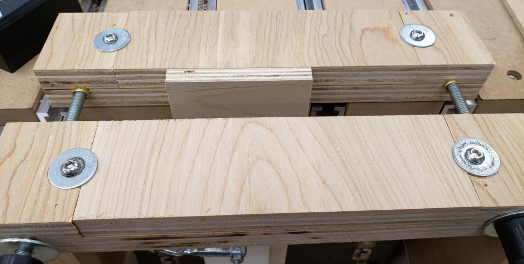
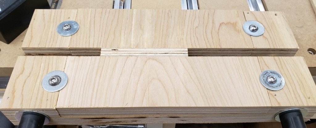
To create the jig I attached two pieces of 34″ plywood to the outside edges of a larger piece of plywood with glue and nails. This would be the base area for the rails/bolts that clamp the two halves together. I will mill it all as one piece and cut it in half at the table saw.
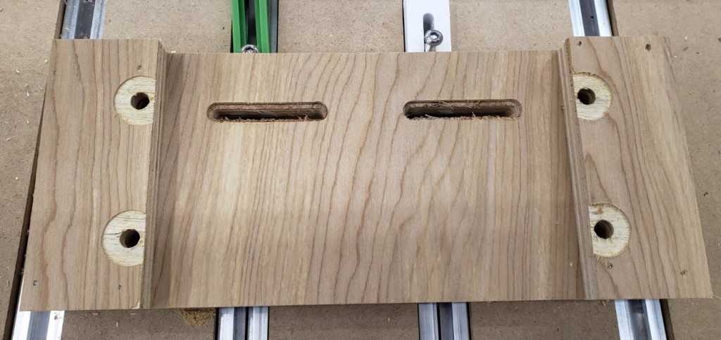
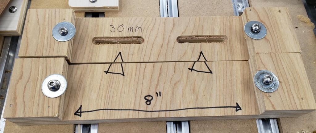
The slots are 50mm long and spaced 100mm apart. That should let me position it anywhere on my table top by always spanning two rails. I started with them just wide enough to hold the bolt head, but eventually widened them to allow washers. Bare screw heads on plywood would eventually compress and allow the jig to rotate.
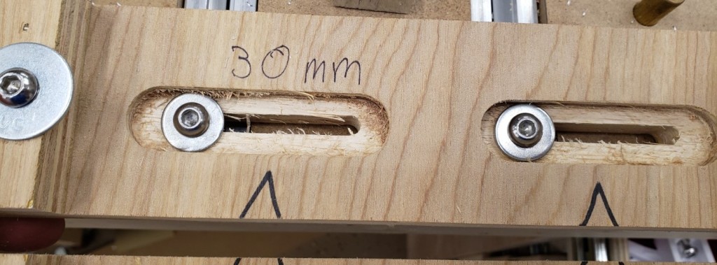
Widened to allow washers

With the milling done, I cut it in half at the table saw, then added some alignment notes. Any 8″ wide piece of 3/4″ plywood or MDF should clamp in there.
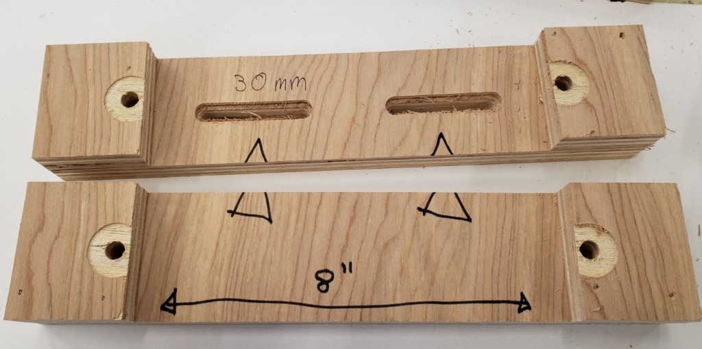
To hold the sacrificial waste blocks I screwed in an M6 threaded insert to the bottom of the jig. Button head screws and fender washers sit in the counterbore and clamp down the waste boards.
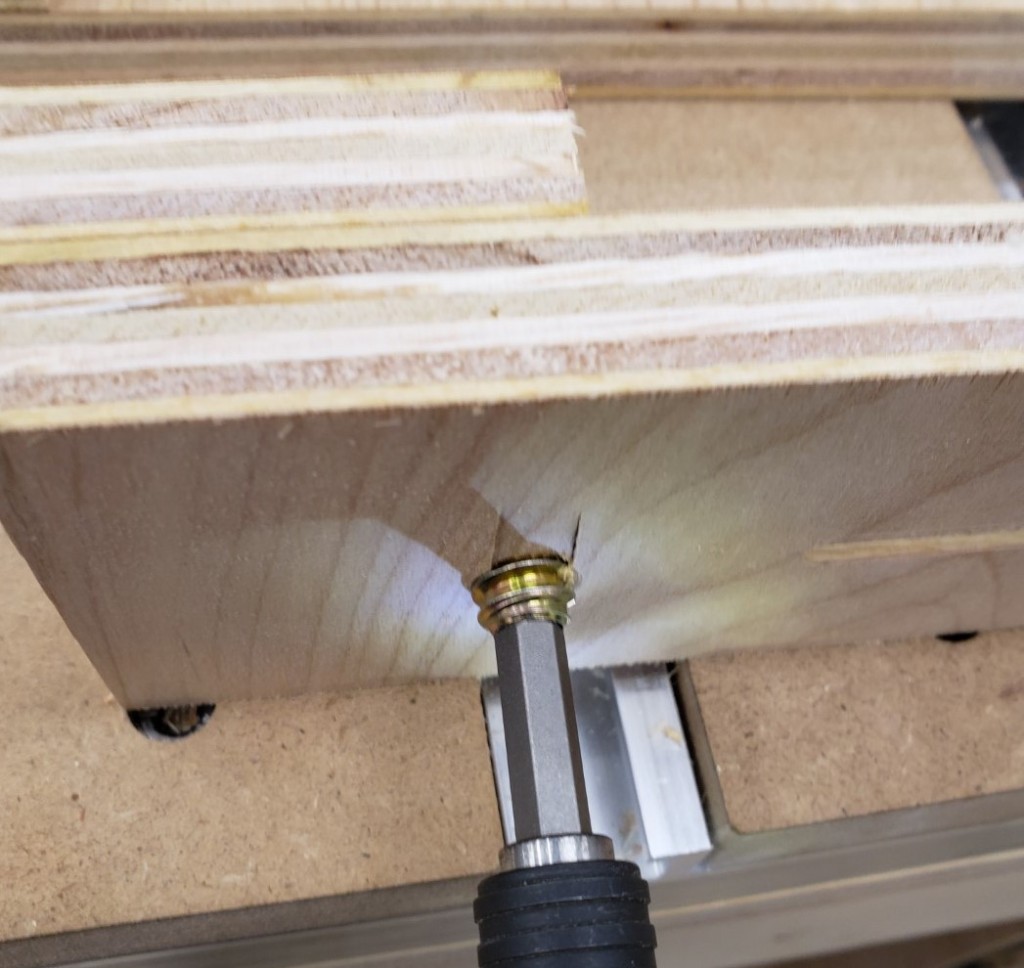
I clamped the boards together and drilled all the way through with a 3/8″ bit. It gave clearance for a 5/16″ t-bolt hammered into the back, and brass tubing in the remaining spaces. This acts as a bushing for the 5/16″ bolt. I used thread locker to keep it secure in the back, then large knobs in the front to clamp everything down.
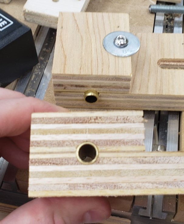
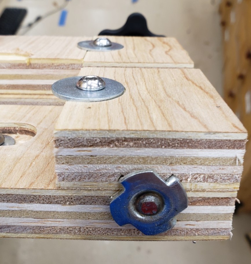
T-nut secures 5/16″ threaded rod

Here it is fully installed without the waste boards inserted yet. You should be able to get at least 2 uses out of a 3″ wide waste board by flipping it around after the first cut pattern. I found mine were in good shape even after making 16 cuts of the finger joint pattern.

This version doesn’t need the cam clamps, the vise like action of the two threaded screws has plenty of clamping power. Similarly, I didn’t need a height stop. I could very accurately feel when the board was flush with the top of the jig. The second round of drawers went very smoothly with this jig!

New Router Mill and Table

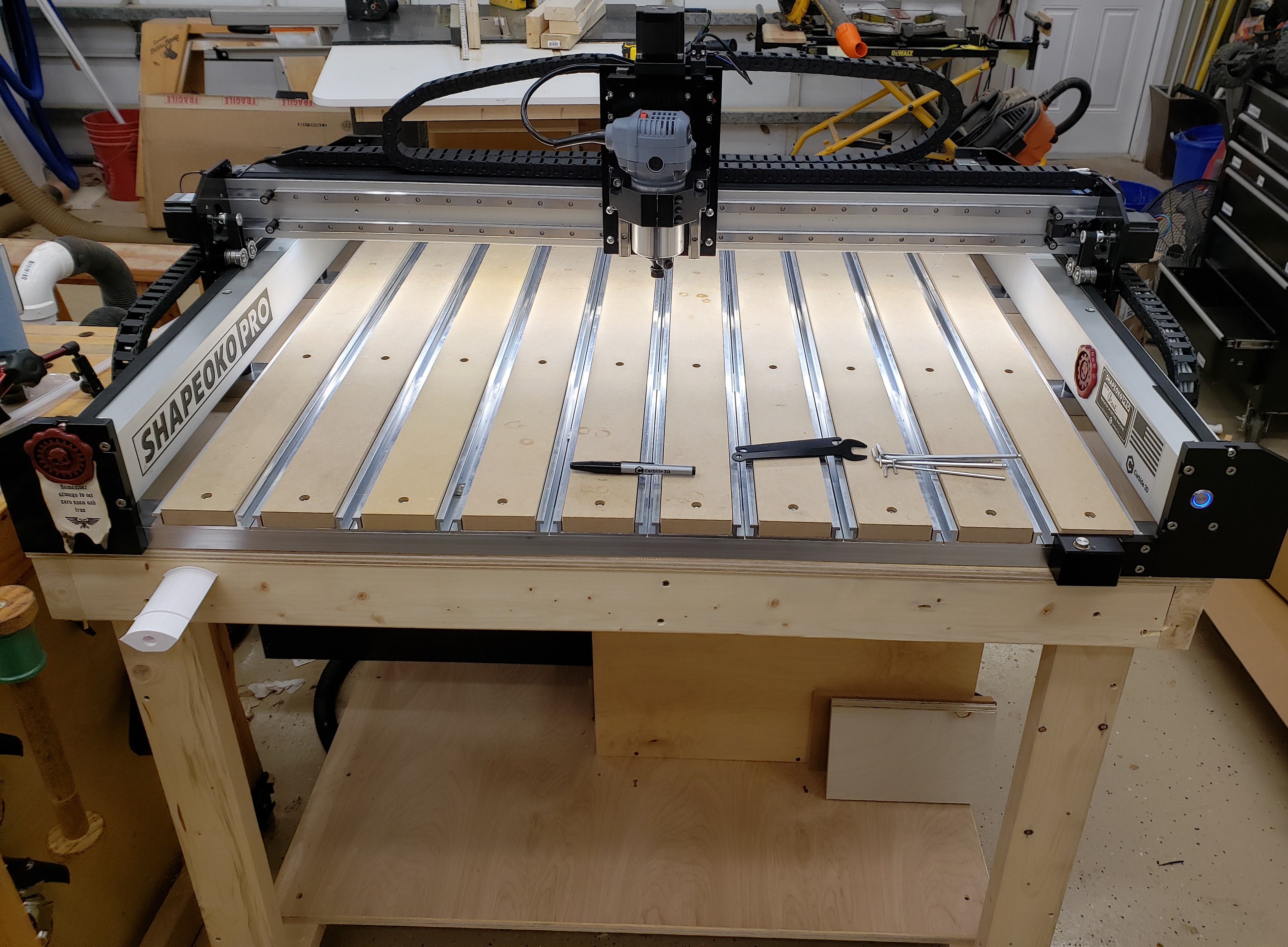
After months of messing with my 3018, I am upgrading to a shapeoko pro. Having owned a shapeoko 2 many years ago, and gained a new appreciation for the power of modern CAM software available to the hobbiest, I was ready to jump in deep. A recent engineering award at work sealed the deal by adding a monetary boost. The 3018 was fun, but kind of a toy. I struggled to get my projects to fit on it, and it was barely able to slog through the oak handles on my material cabinet.

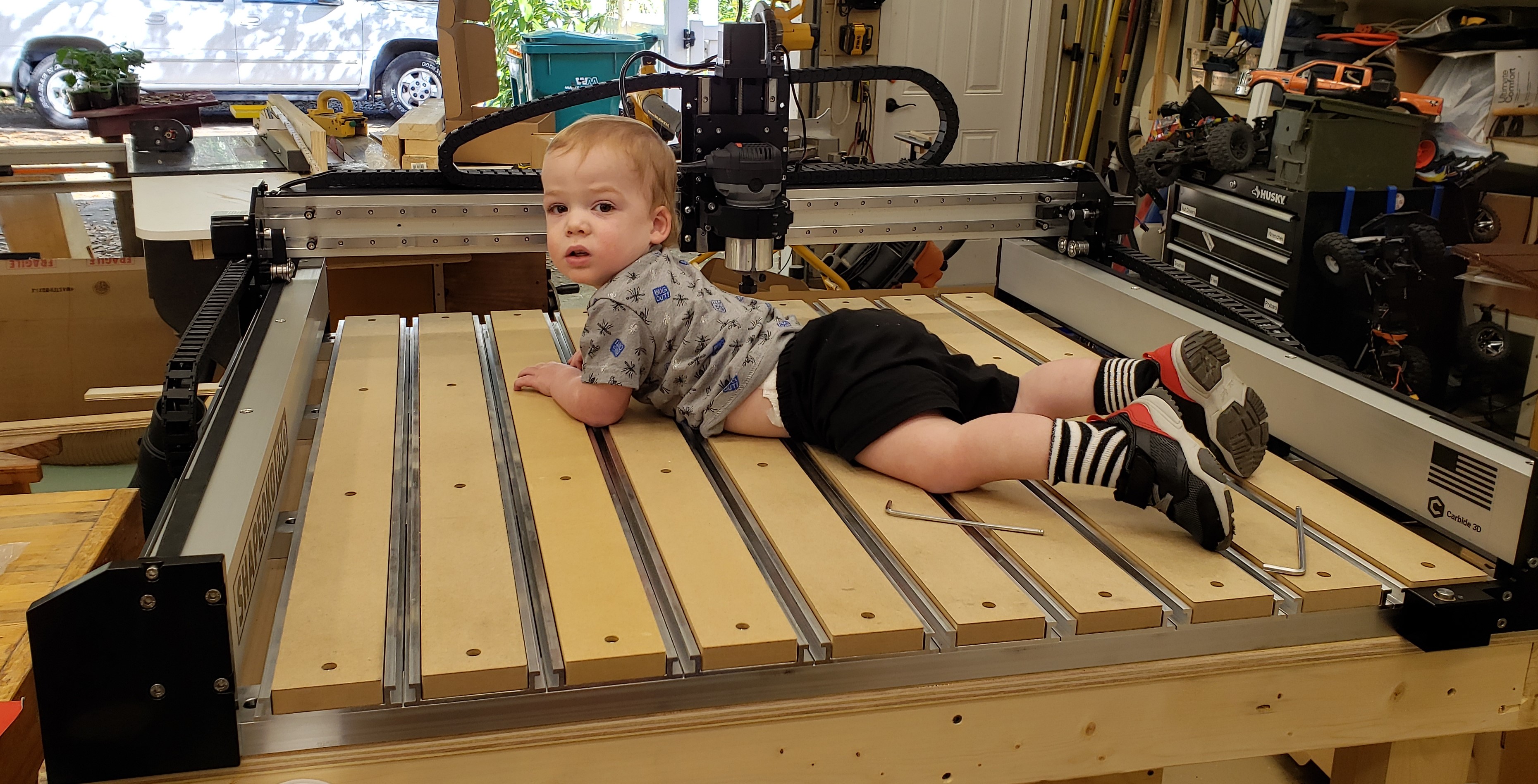
The new tool is a big beefy bad boy! So big in fact, I had to use a toddler for scale. He is 32″ tall, and this thing can cut a 33″ square. Everything about it is designed very stiff compared to any of my previous mills, and I think to get something better would require a custom build or doubling the price tag.
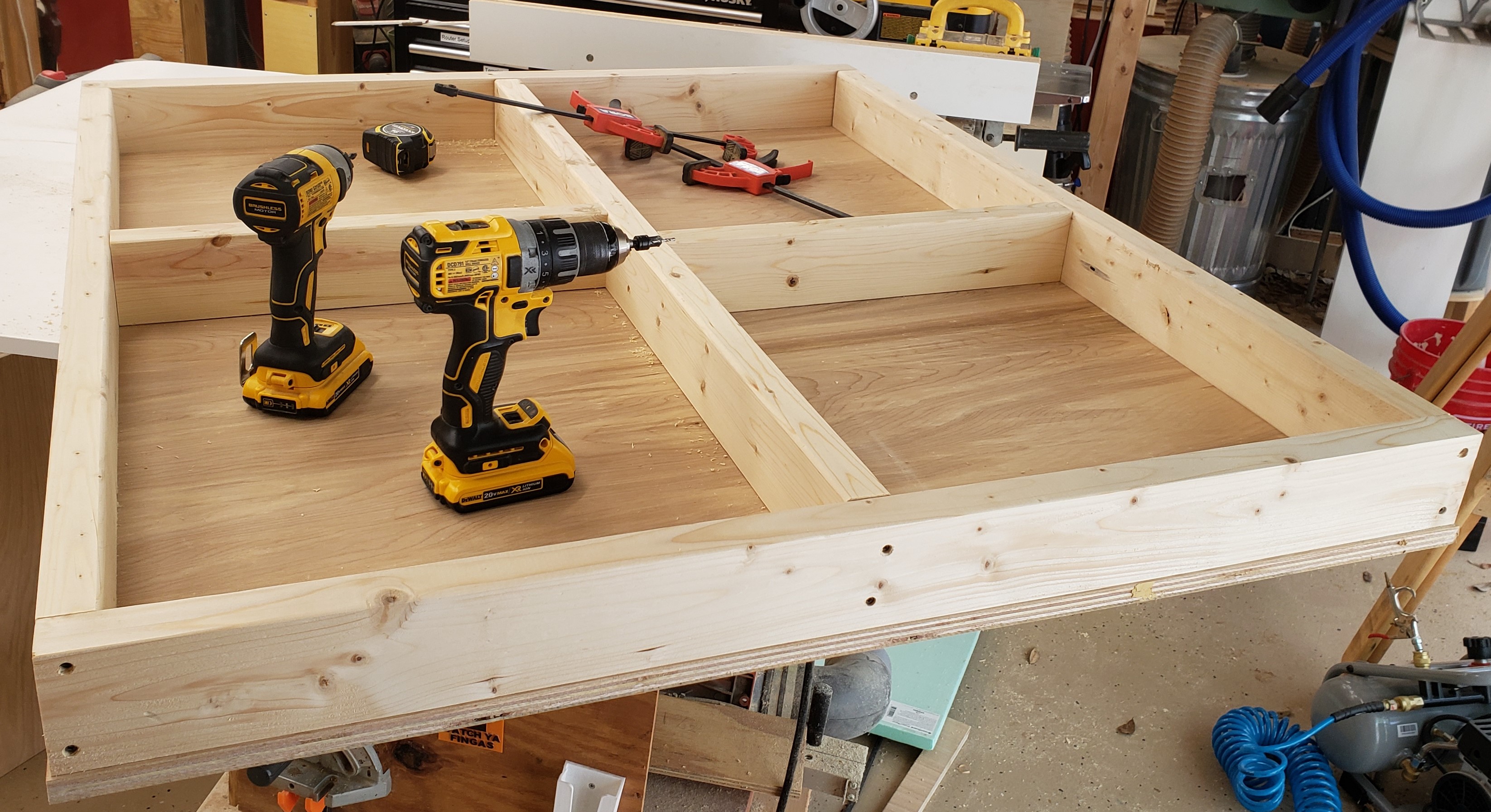
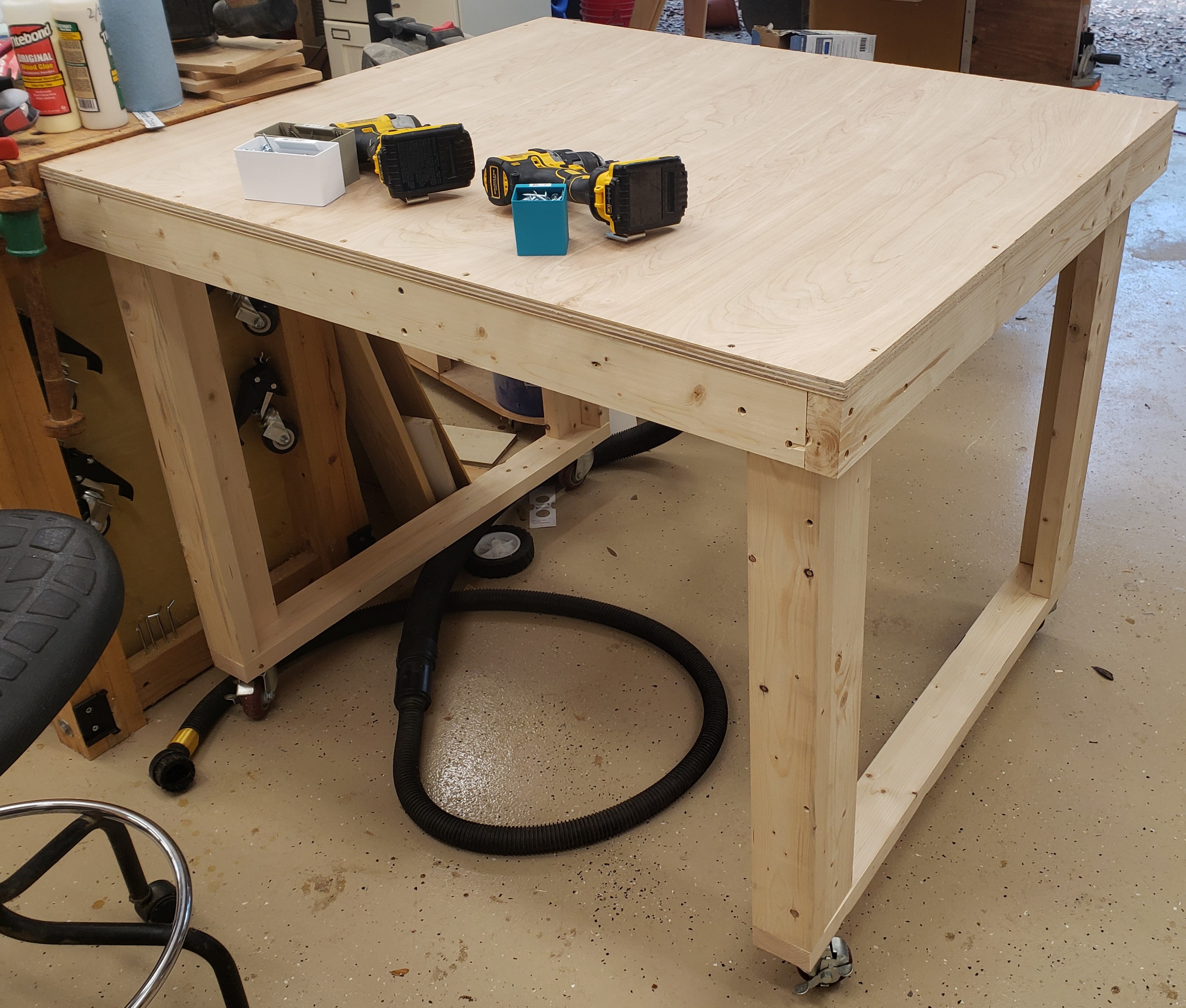
A big CNC router requires a big table. I moved a lot of shop things around in my head until I decided I could actually fit this beast. My woodworking bench had to scooch over a smidge, but there was room, and it keeps the mill in close proximity to my computer stand.

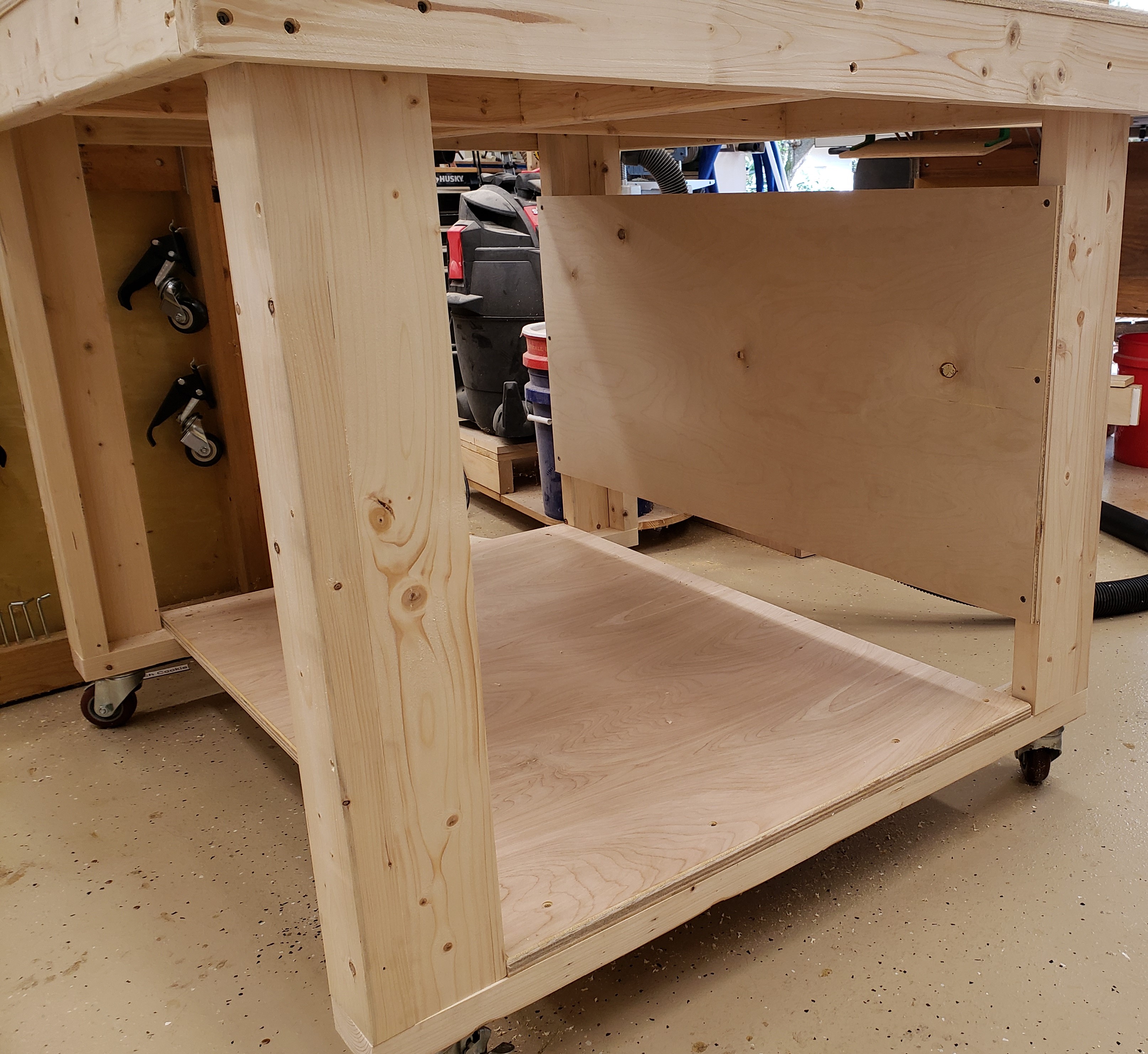
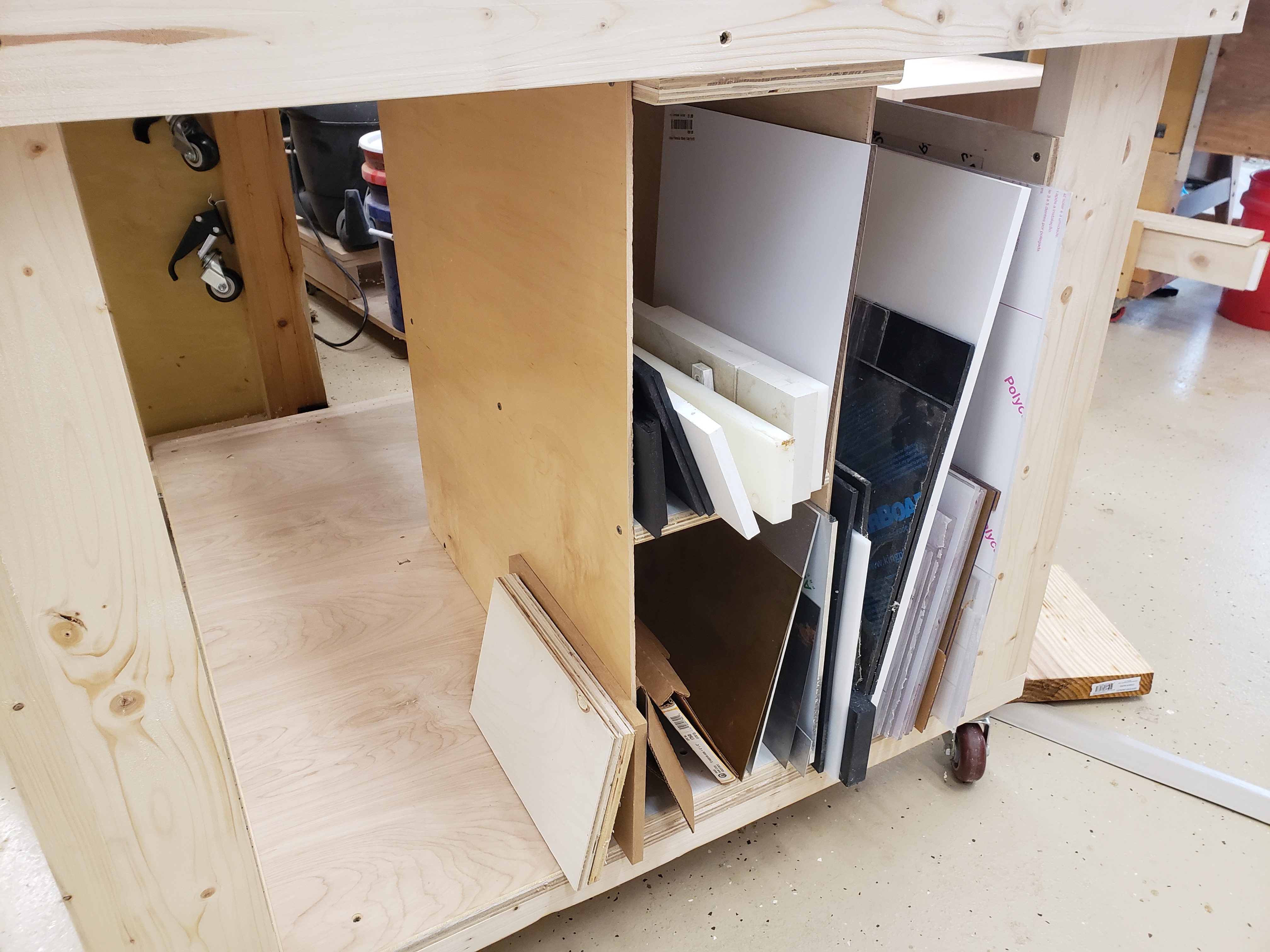
I was thinking torsion box originally, but only put a top on it. I started by running some 2x4s through the planer to get them flatter and squarer and all at an even set of dimensions. The top is 3/4″ plywood with the legs two 2x4s at right angles. I put it on casters because everything in the shop is required to be on casters. I threw a level across the top of the table and it was quite flat until you got to the edges of the plywood. That should hopefully be a good enough base for the mill. The bottom has storage area for all my plastics and metals with room to spare. I’ll probably put together some drawers once I live with the table for a bit and see where I naturally sit/stand.

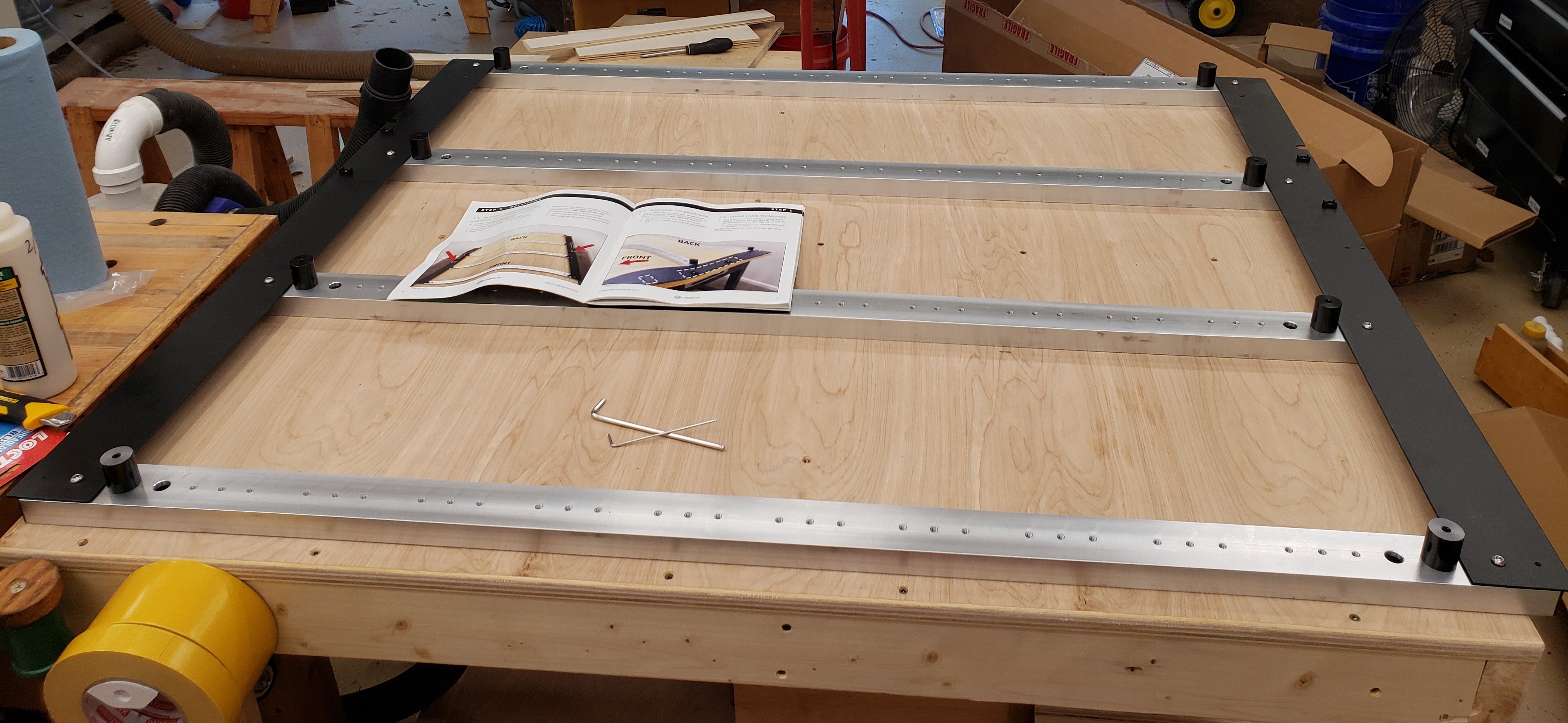
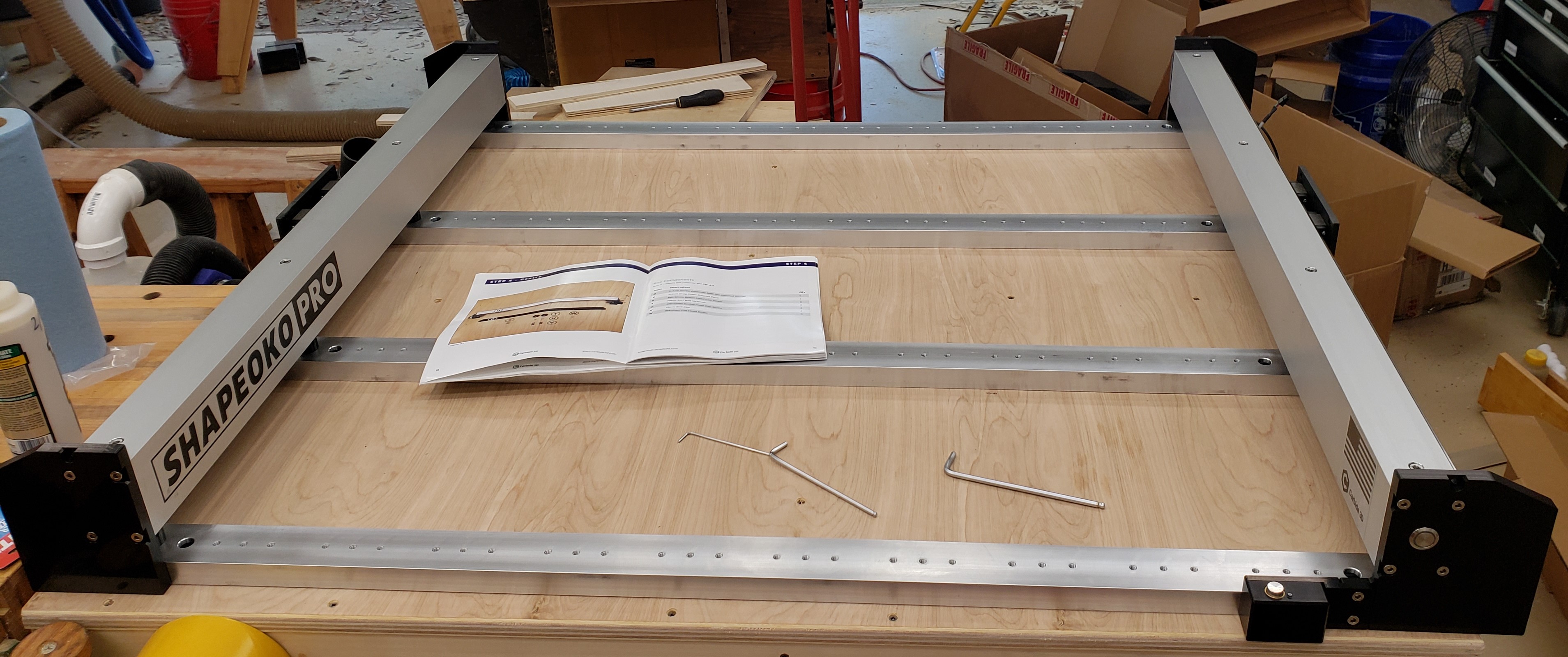
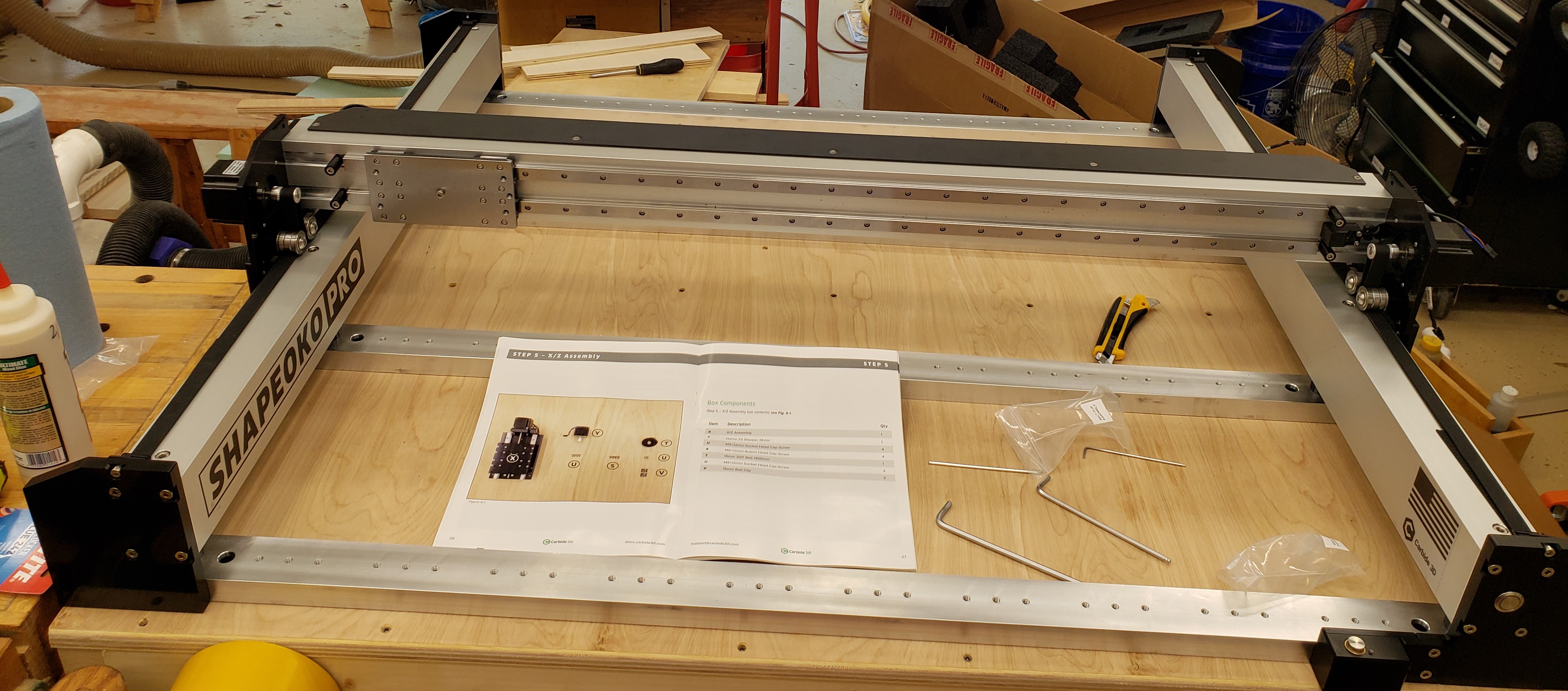
The build was delightful. Good instructions, simple assembly, high quality parts, and only took a few hours. This thing is over 150 pounds of metal! My only hitch was that they sent me the wrong spindle and some headers on the controller board were installed upside down. They eventually made that all right via tech support.

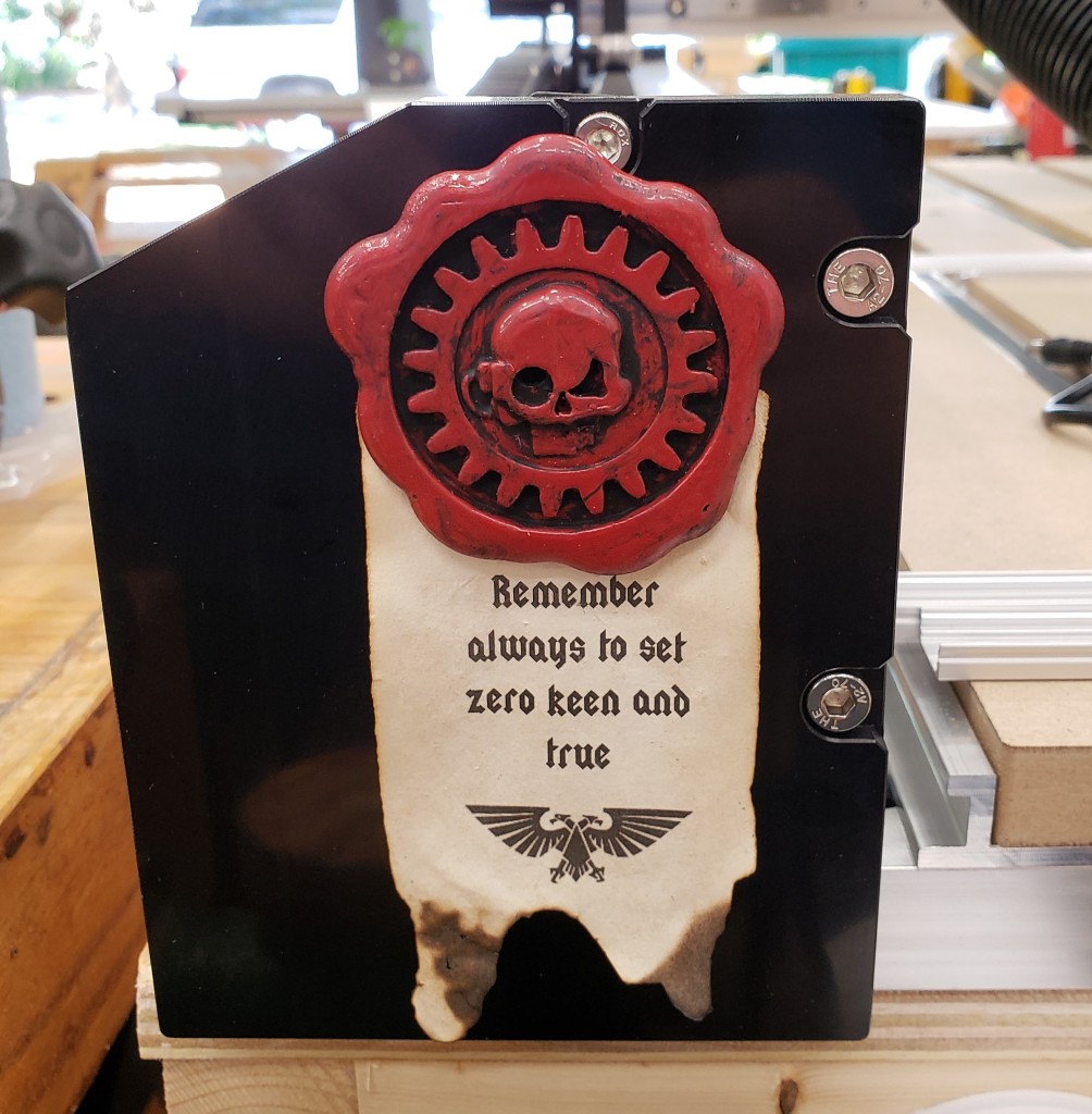
I added a set of double LED strips under the X rail to help light up my projects. I expect a home made Z-touch probe and different dust collection solutions is in my near future. Regardless I got it all setup and blessed by the tech priests of the adeptus mechanicus. A coworker got me reading warhammer 40k, so I had to do some crafting for myself and him as a gift.

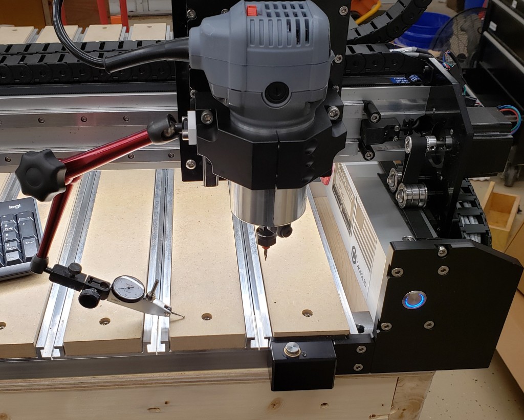
I got the new control board installed today and couldn’t help but start by measuring the stage accuracy, table flatness, and XY squareness. All of the numbers have been fantastic. I just have to check the spindle tram, then we are off to the races. I did try some test cuts in MDF. It was flying like a hot knife through butter.

Materials Cabinet

In industry there is a line of drawer cabinets from a company called Vidmar. They can be short or tall, but are usually pretty wide and deep and super well built. Each drawer can hold hundreds of pounds, they have different divider systems, and full extension drawers. Also they tend to have fancy features that don’t let you pull out too many drawers. You could easily tip one over on yourself and cause serious injury.

In looking at my materials storage area, I have a lot of plastic bins that are organized, but maybe only half full. I have made hardware drawers in the past and love their organization and dense storage capacity. This new cabinet will be much larger and deeper and use full extension metal slides. I started with a lot of planning. I wanted to maximize the materials I used, my limited shop time, and the space available.

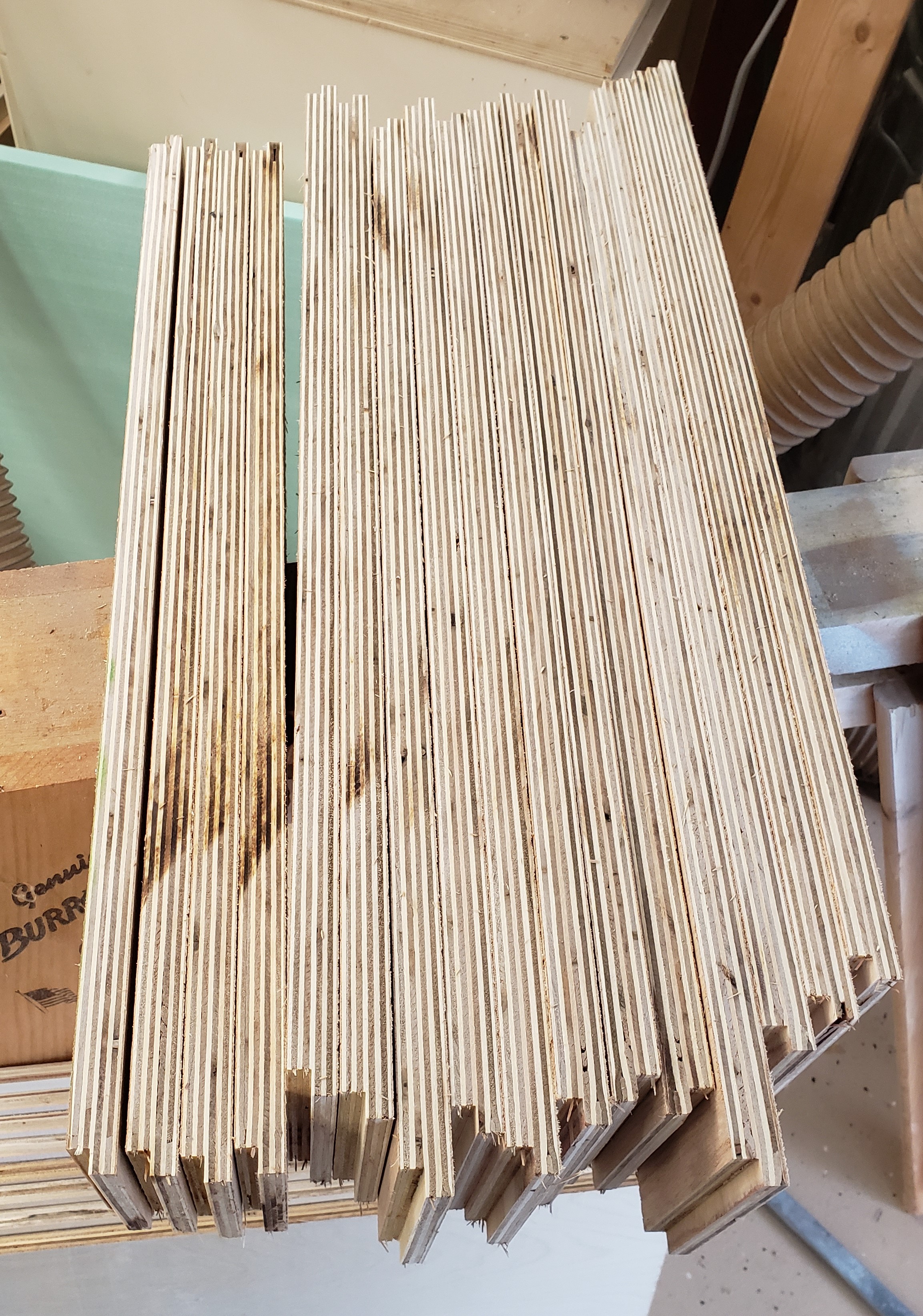
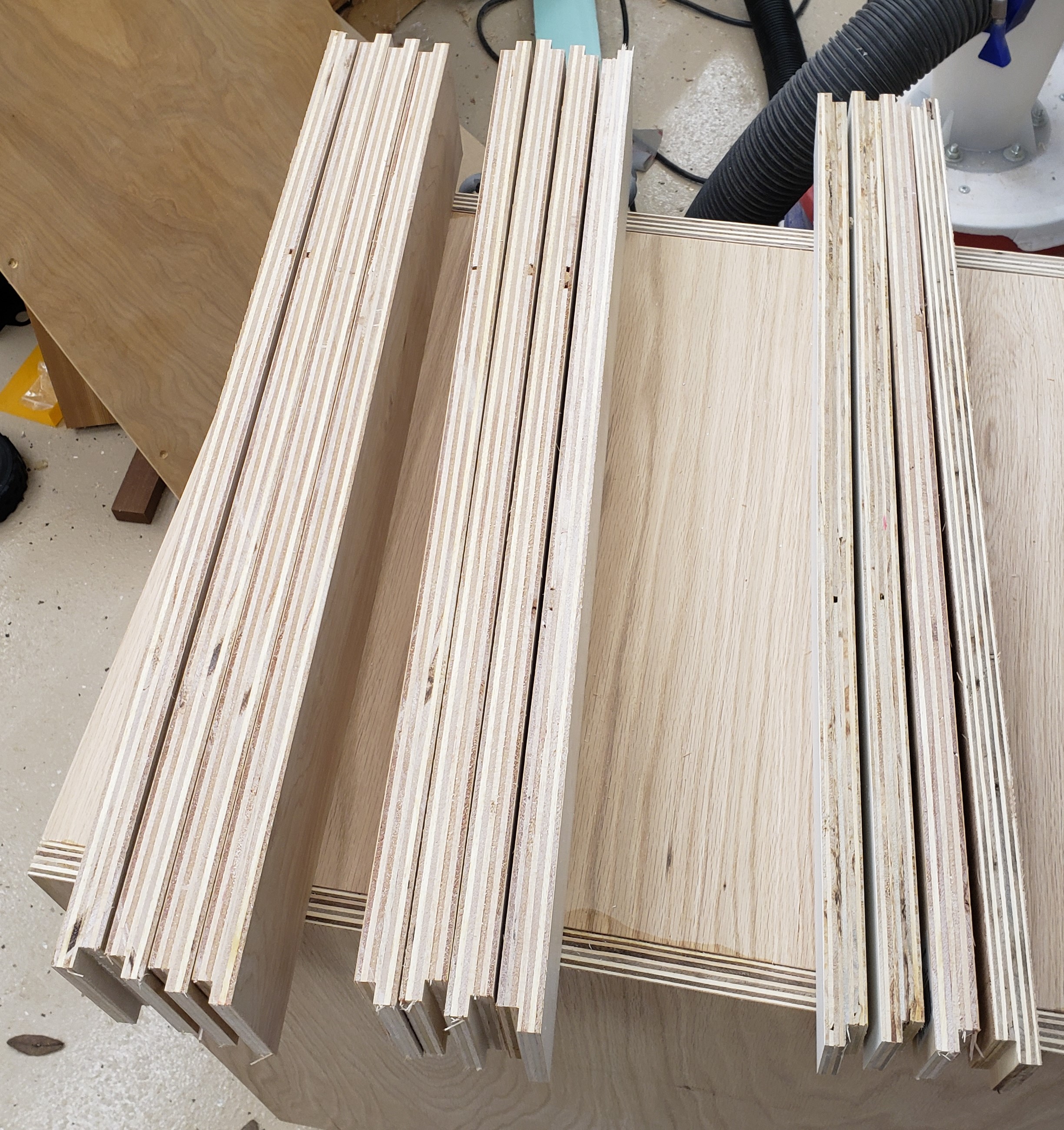
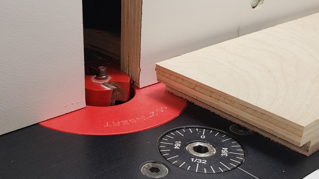
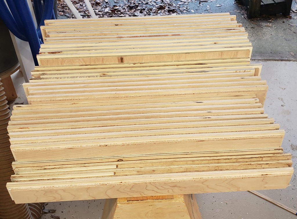
I had it all worked out on paper, and started with the drawers. I cut 24″ wide sheets of 3/4″ plywood and put a rabbet down two sides to make half lap drawers. All four sides of the drawers would all be the same length. This made batching easier. Routing bulk material was faster and cleaner than cutting out individual sides, then doing the routing. This was a big improvement over previous drawer efforts.

Rabbet for the half lap

With all the sides cut, I put another rabbet along the bottom of each board for the drawer bottom. Each would get a 1/2″ piece of plywood in the recess. Probably overkill, but I want them to be able to handle a lot of weight. Eight 24×24″ drawer bottoms worked out nicely to 1 full sheet of 1/2″ ply. It was subtle, but I put a little radius on the top edges of all the drawer sides to make it easier on your hands when reaching in. They took a bit of sanding to smooth out.

Routing for drawer bottoms
Slight radius on drawer side top edges
All drawers ready to assemble

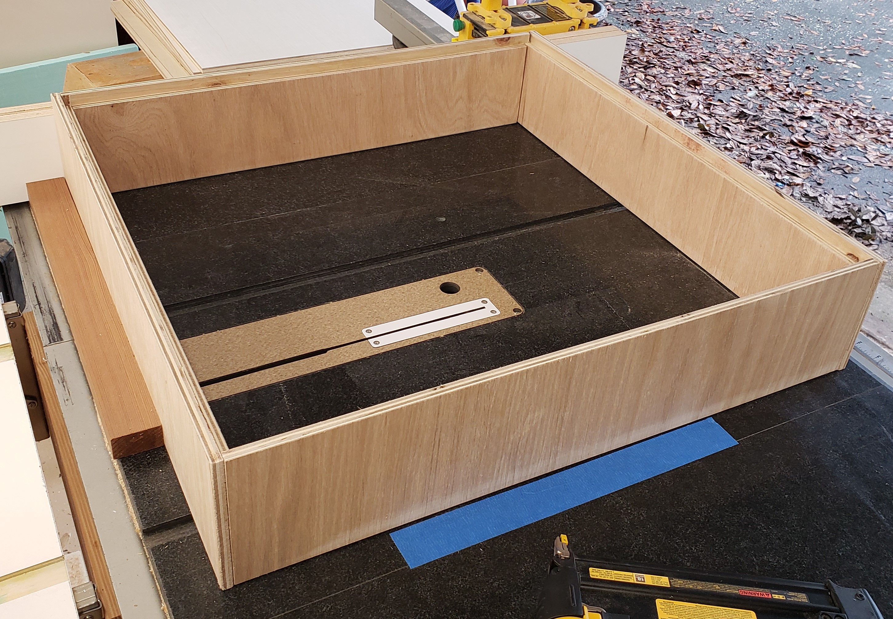
I had everything figured out really precisely, and cut all the drawers at the same time to reduce error. If they went together with any kind of bows or warp, it would throw my plans off. I attached a board to my table saw to act as a square, and used the top as a large flat assembly surface. Each side got glue and nails in two directions. Nailing and gluing a half lap like this is really fast, easy, and strong. The drawer bottoms got glue and nails in from the bottom, and into the side of the bottom plywood. They were fast to assemble, and should be bomb proof!

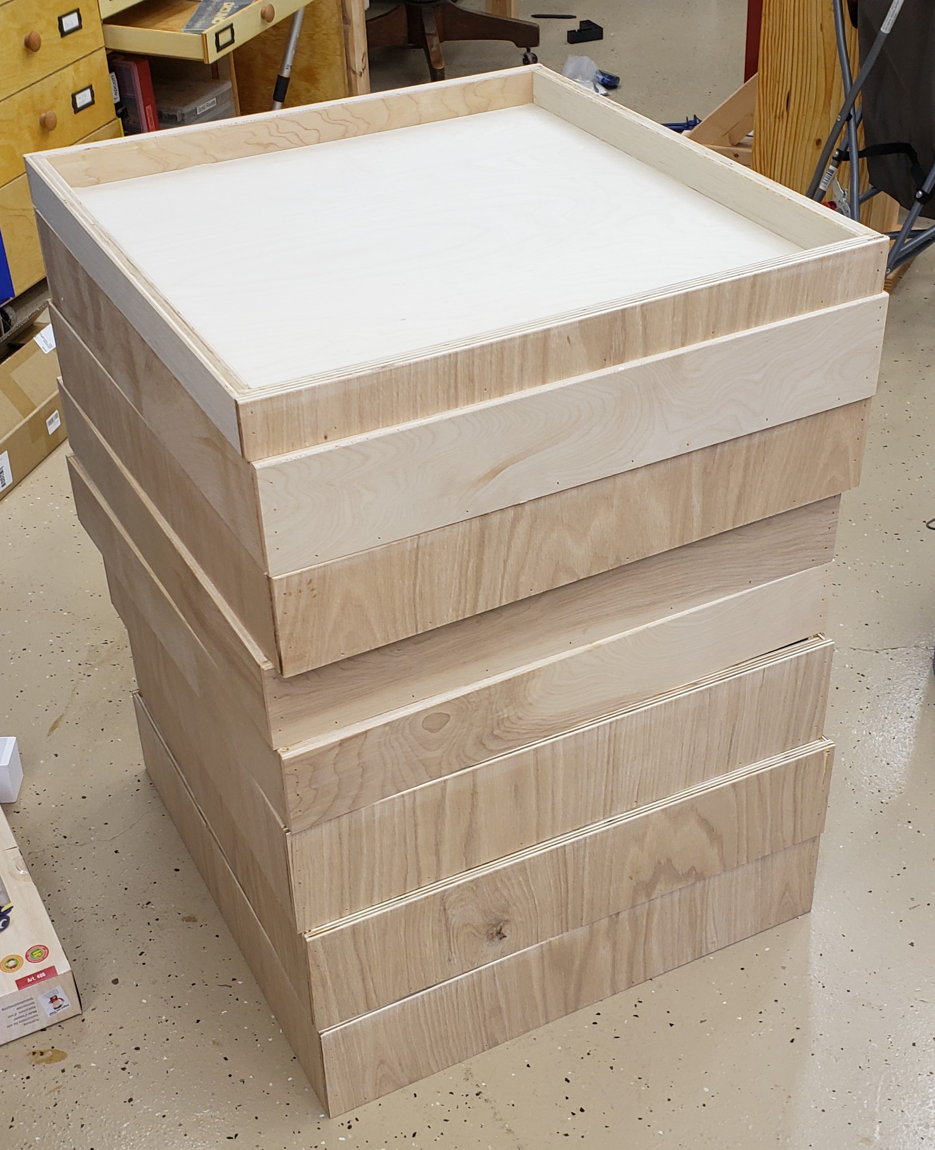
For the drawer fronts I cut a single strip of 1/2″ plywood and aligned each front with numbers so the grain flows naturally from bottom to top.

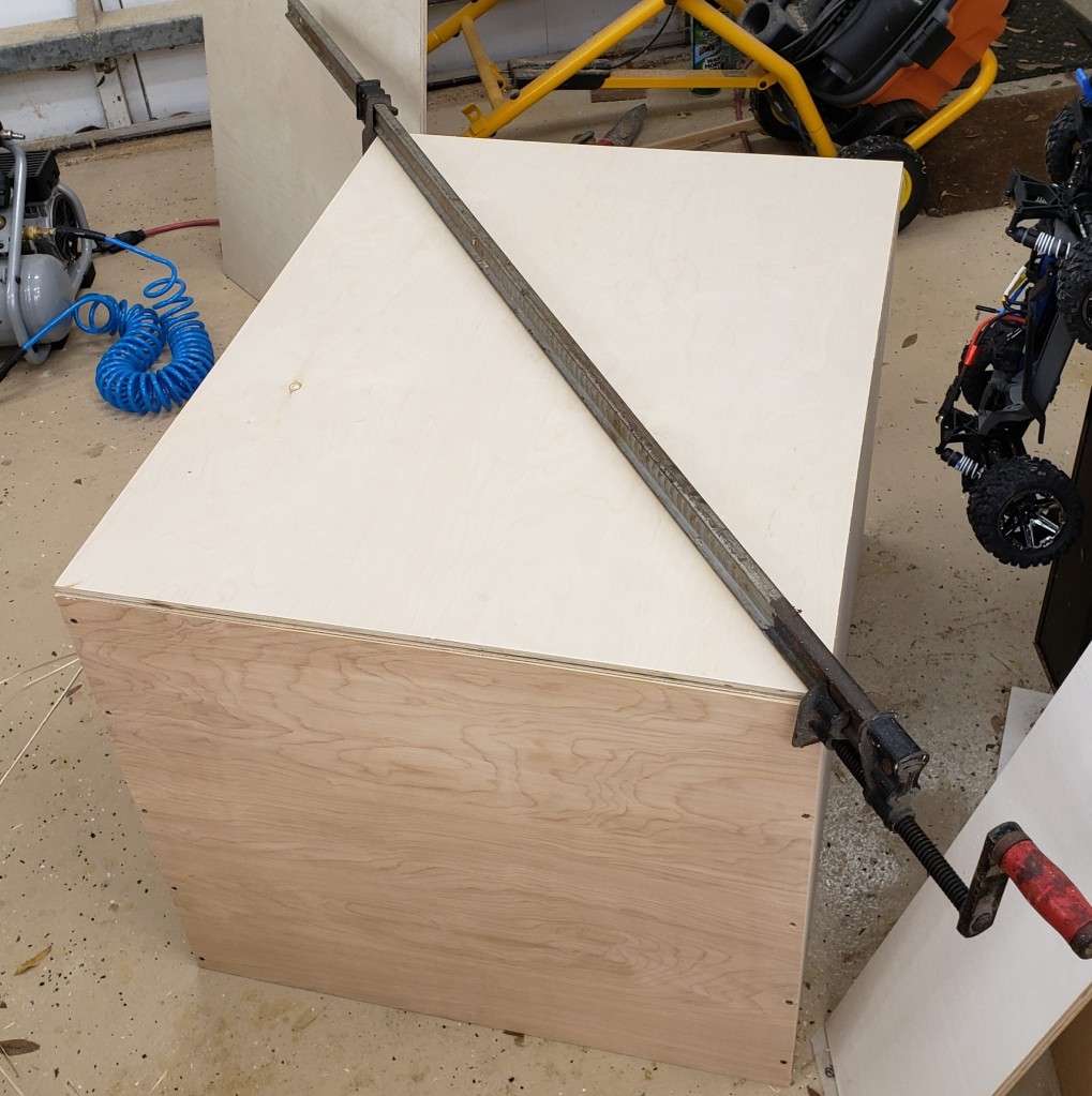
Next came the carcass of the cabinet. Nothing special here, just a box with an open front. I had to be very precise though, if the sides crept in, I couldn’t fit my drawers, and if it got too tall, It wouldn’t fit in the right spot in my garage. I had a little squareness issue, and had to break out my biggest clamp to fix it while installing the back.

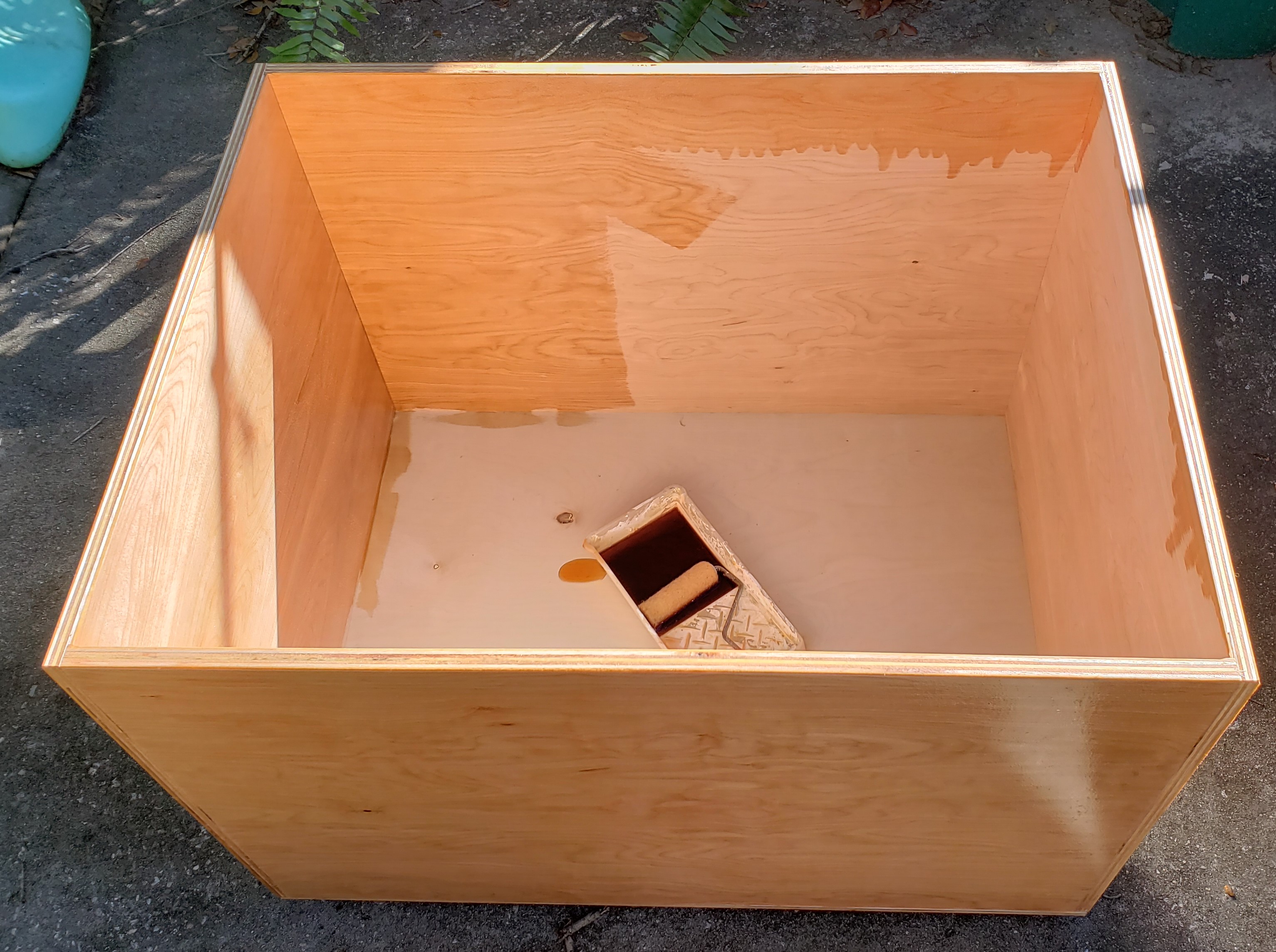
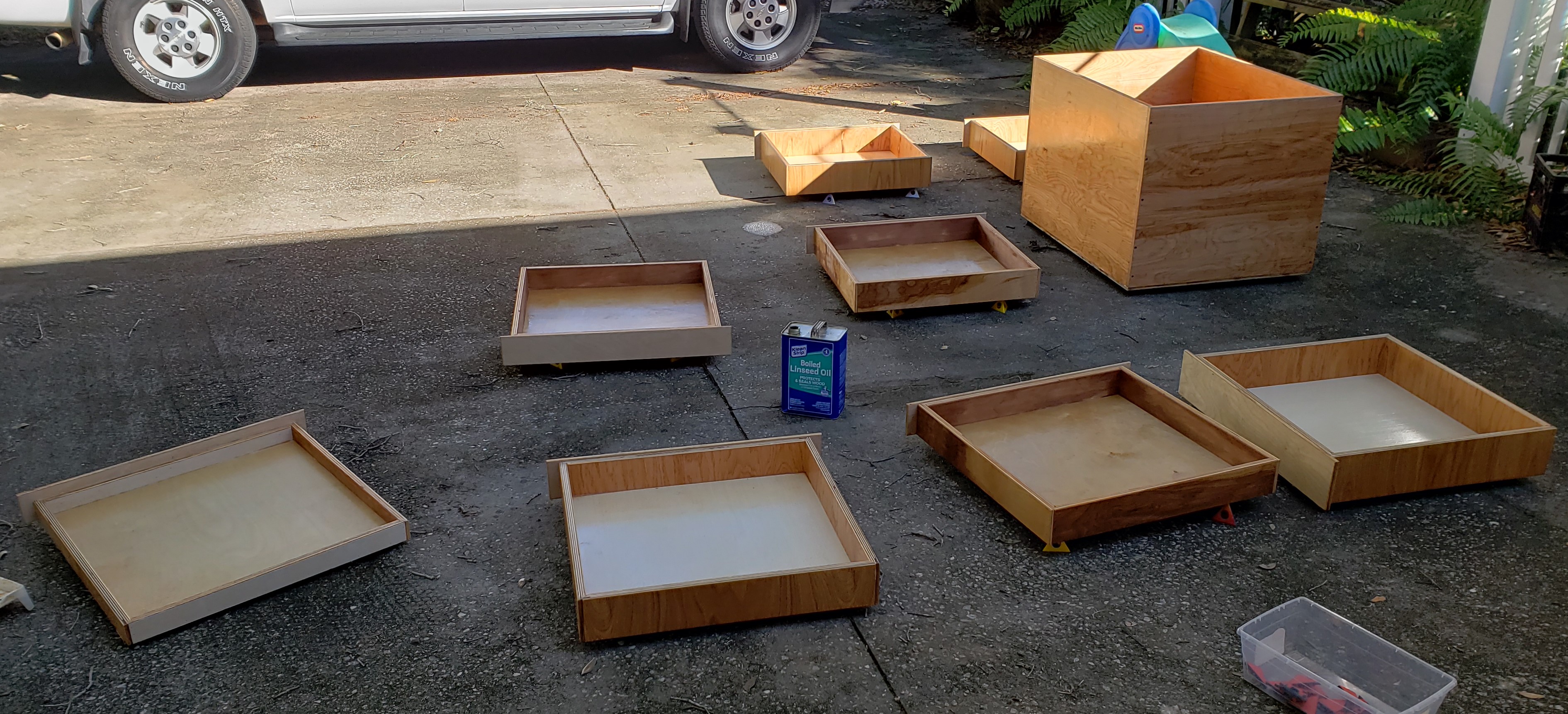
For finish I turned to my usual boiled linseed oil shop tool finish. There was so much to do I broke out a roller and tray to put it all on. I think I went through half a gallon to do the cabinet and drawers. My shop helper was sprinkling the painter pyramids all over the driveway for me to step on.

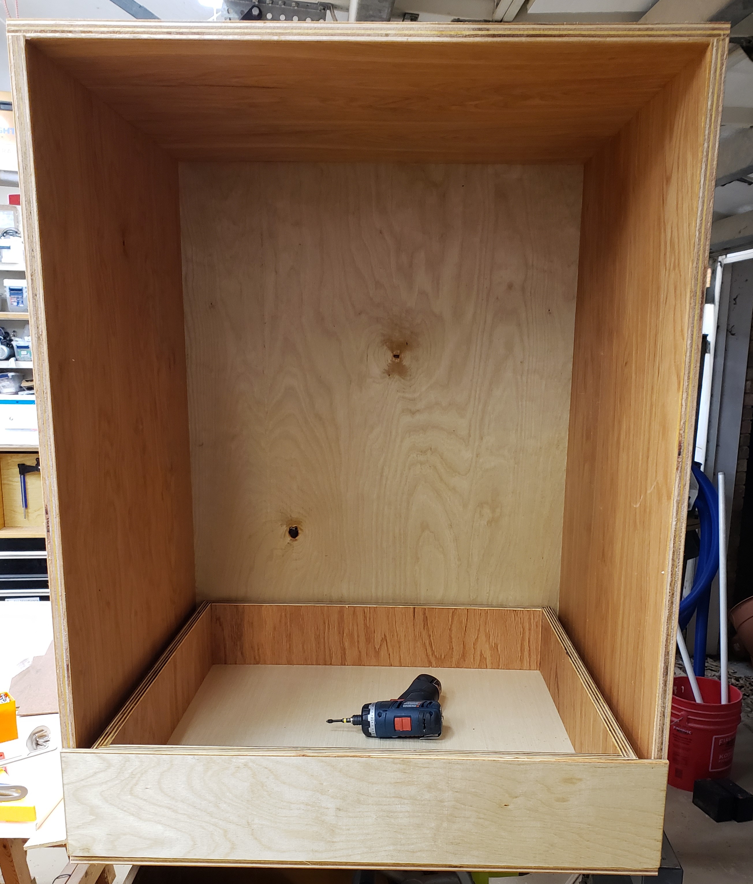
A few days later when it had all stopped smelling I started assembly. The bottom drawer was numbered, and went down with a small spacer between it and the floor. I installed the hinges, then slowly pulled out the drawer and attached the runners. With the first drawer done, I put a 1/2″ sheet of plywood down to provide proper spacing for the next drawer to sit on top of the first. The runners go on the cabinet at a set height, then the next drawer goes in for installation. That gets washed rinsed and repeated until all the drawers are in.

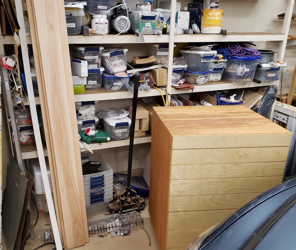
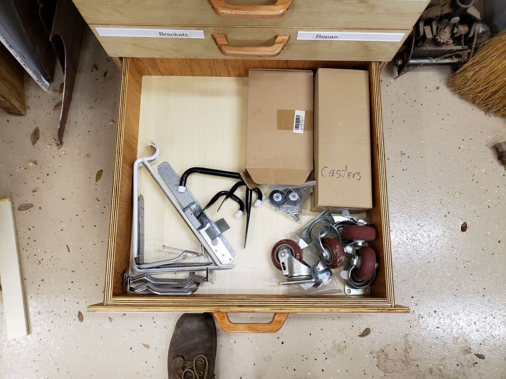
Next comes the home for this big fella. I put heavy casters on the bottom so I could roll it around to clean underneath or rearrange easily. It cost a little storage space, but who wants to bend down that far anyways? Here is the cabinet next to its final resting spot.

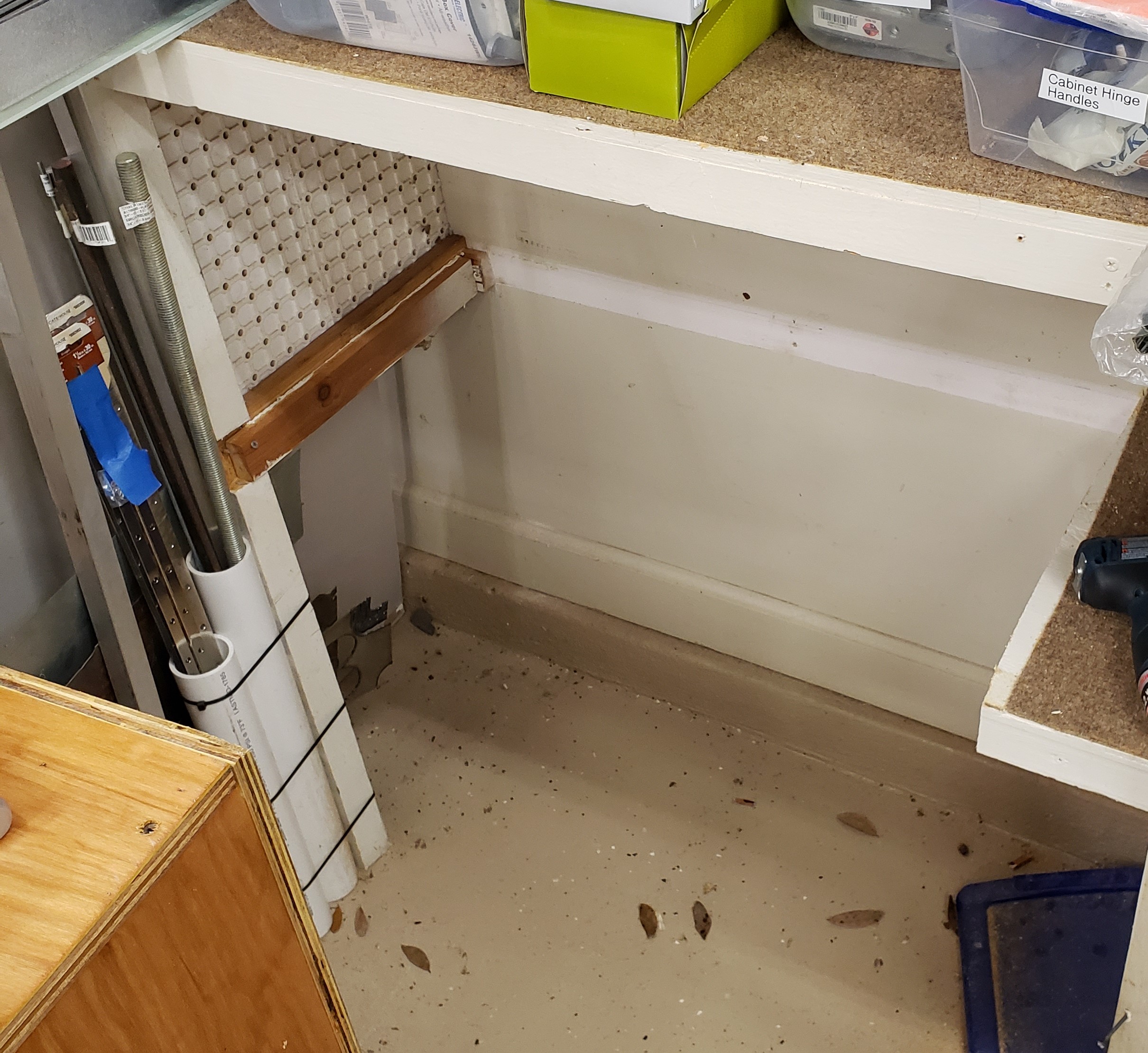
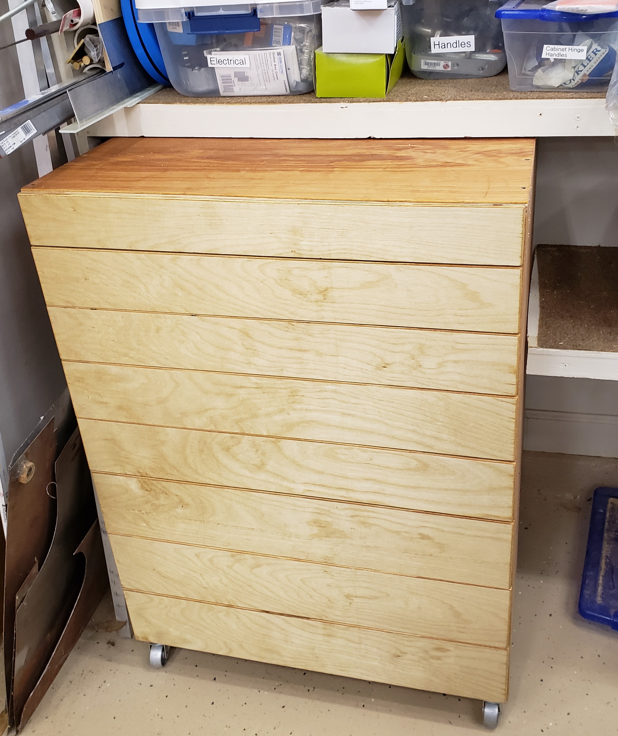
Yes it is a mess, that is why I need this cabinet. I cut out the bottom shelf and slid everything home. I had planned it perfectly. The drawers all fit, the drawer fronts align well, and the cabinet fits up to the next shelf with only a tiny bit to spare.

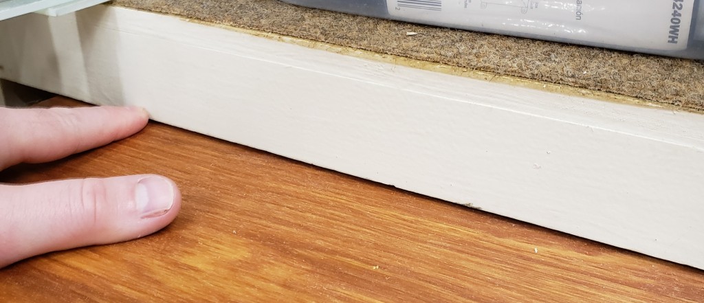
Gap between the top of the cabinet and the next shelf. Less than 1/8″

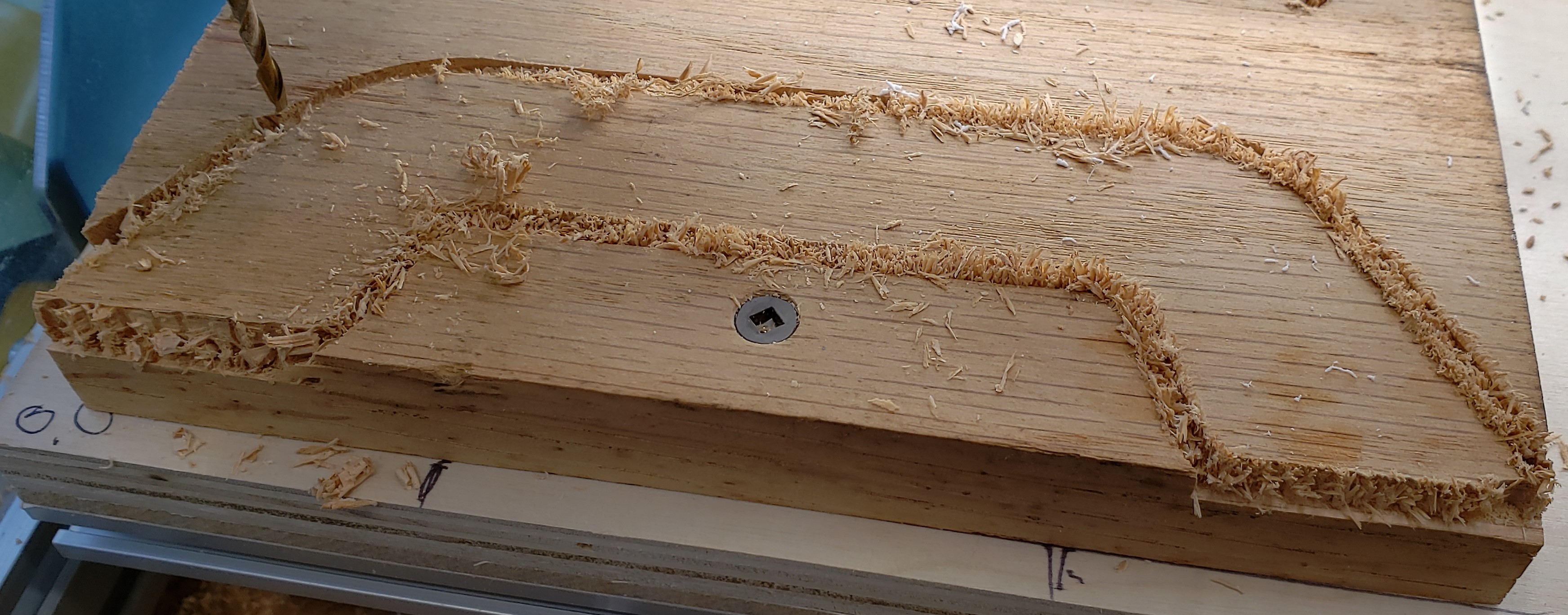
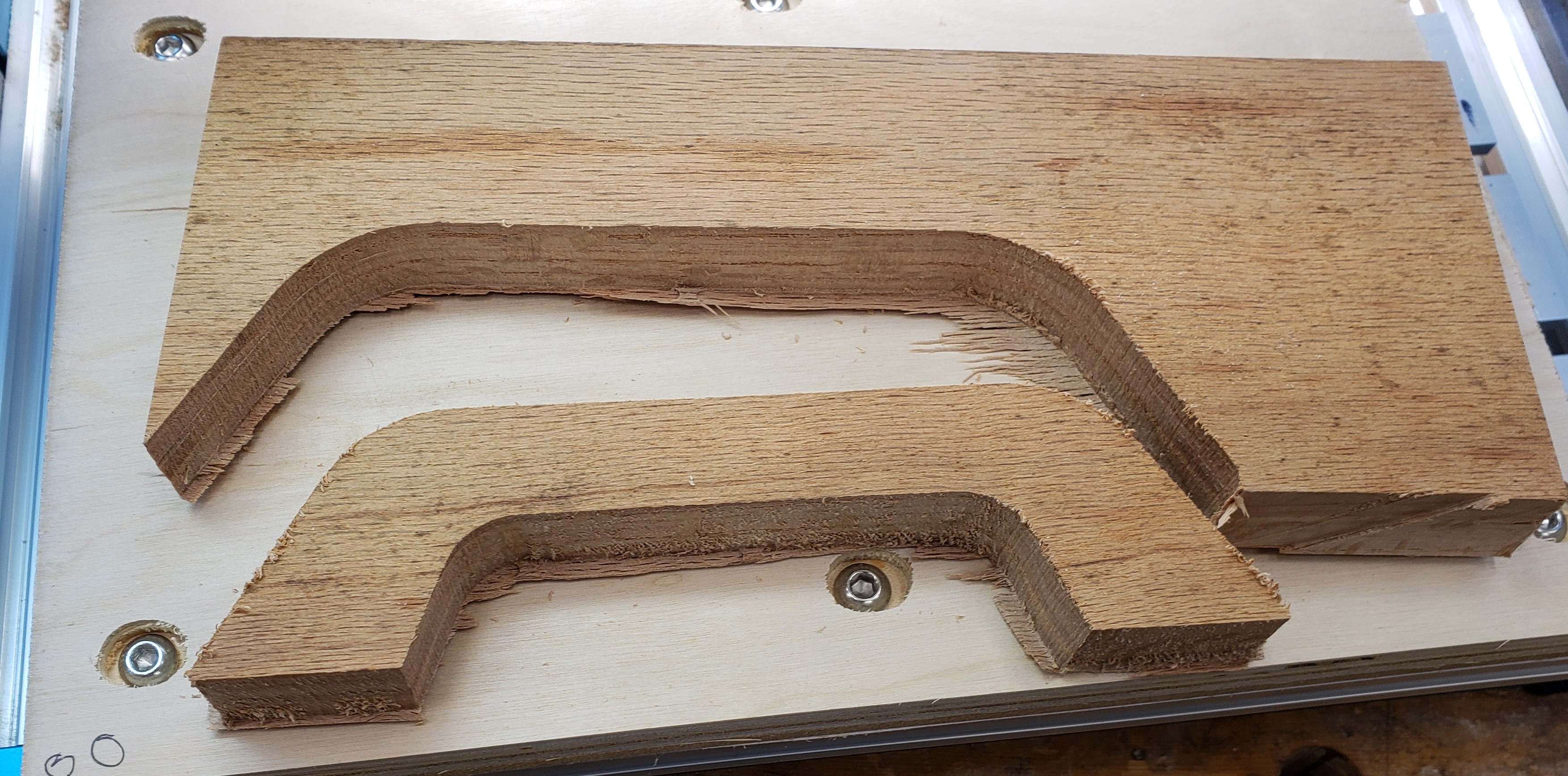
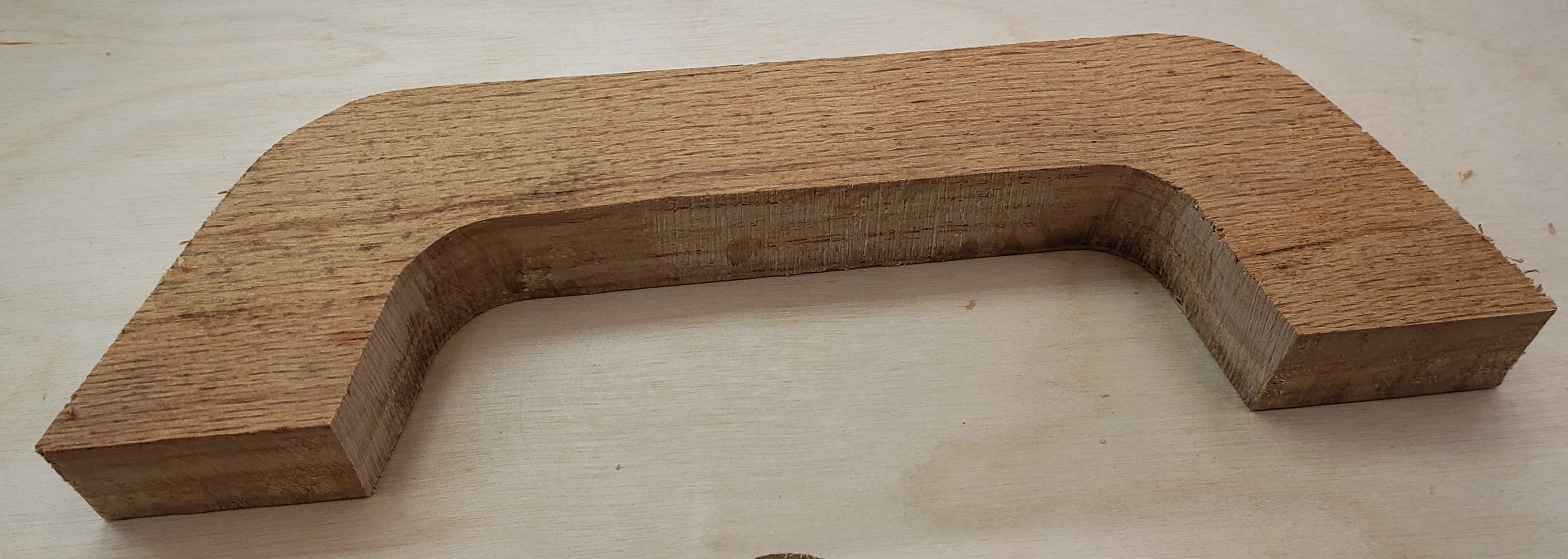
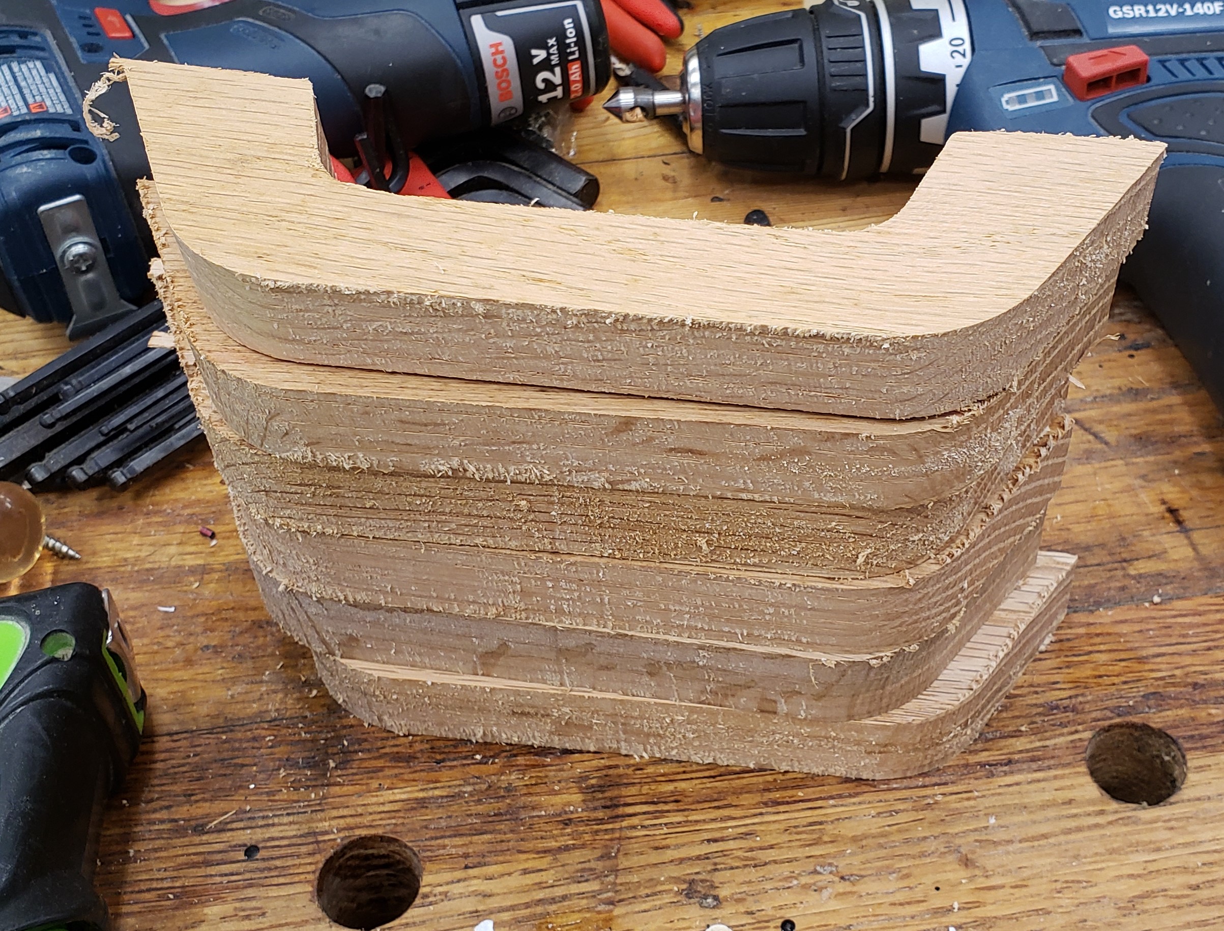
Drawers of this size need a good beefy handle. I employed my mill to cut a nice looking handle shape. It was a bit more of an ordeal than I thought it would be. The machine really bogged down in oak, and a number of them broke off the double sticky tape before finishing. After numerous failures I got the feeds set slow enough and incorporated a screw in the work holding.

To keep from drilling tons of holes in my waste board I made the first operation to drill a hole for my screw, then pause the program. That drill operation is quick, and doesn’t stress the double sticky tape. With the screw installed in the same space every time, I reused the hole in the waste board, and knew it would be out of the way of my cutting. The results were rough, but they worked.

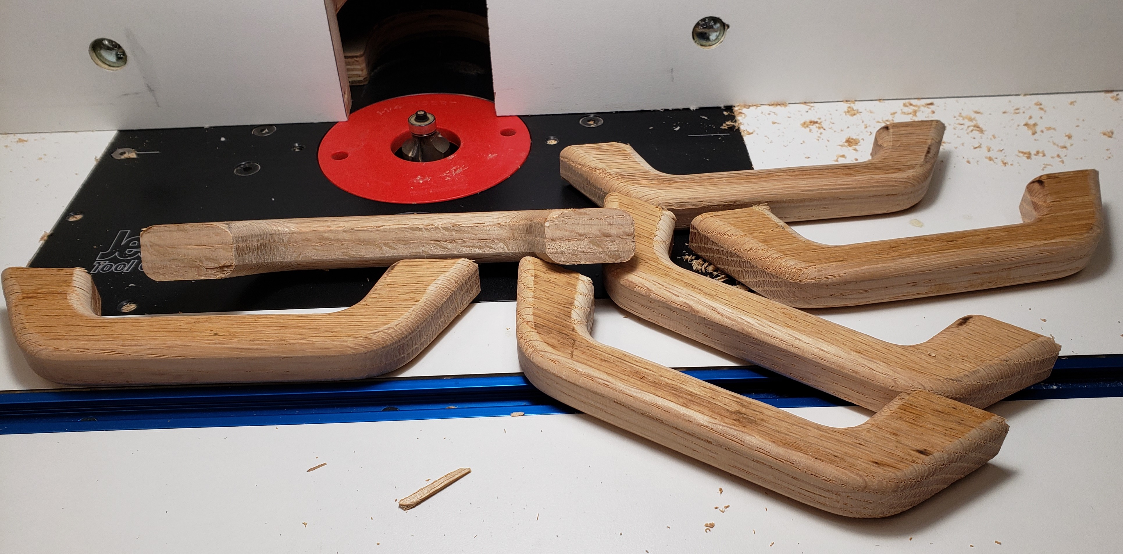
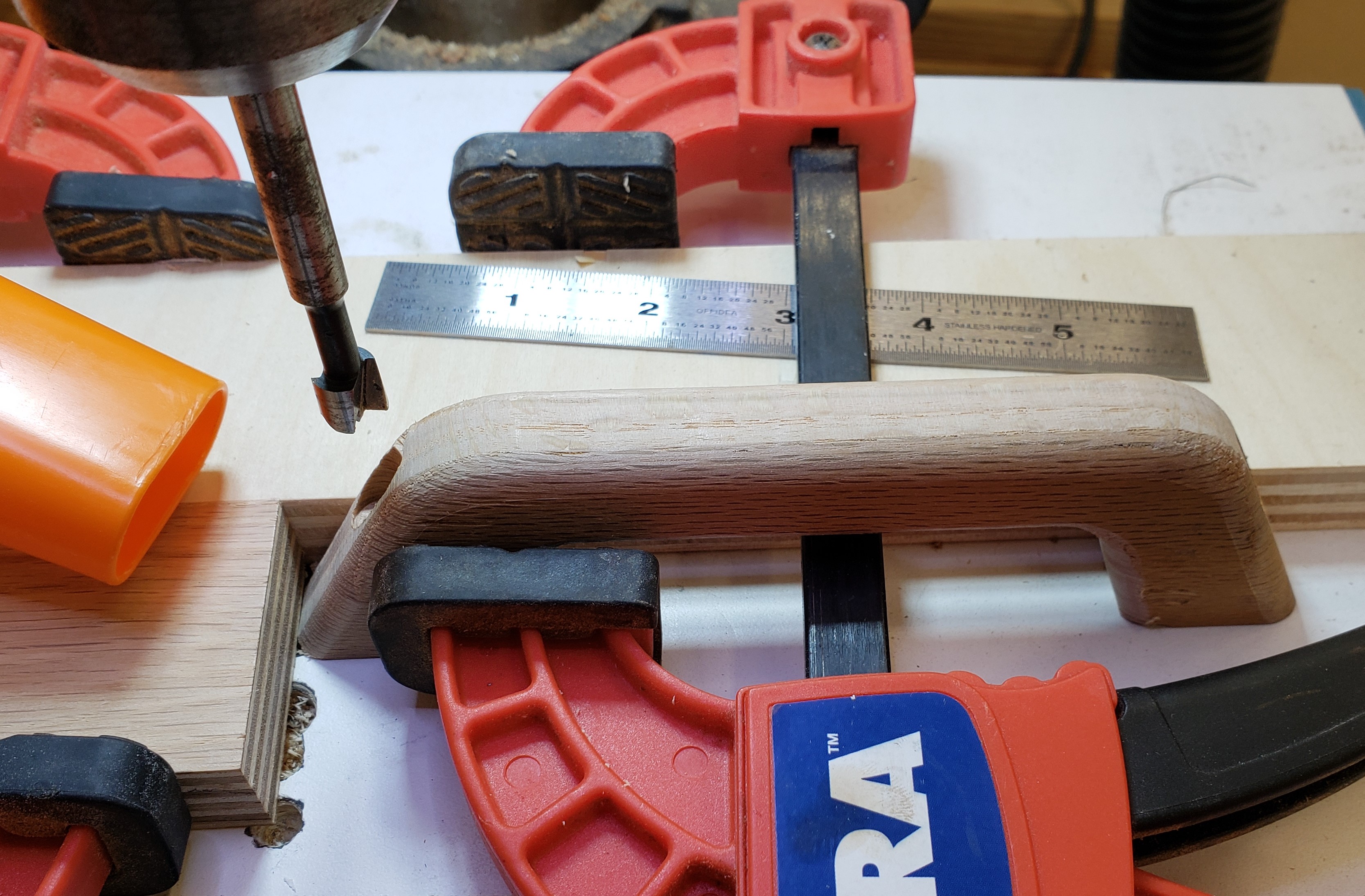
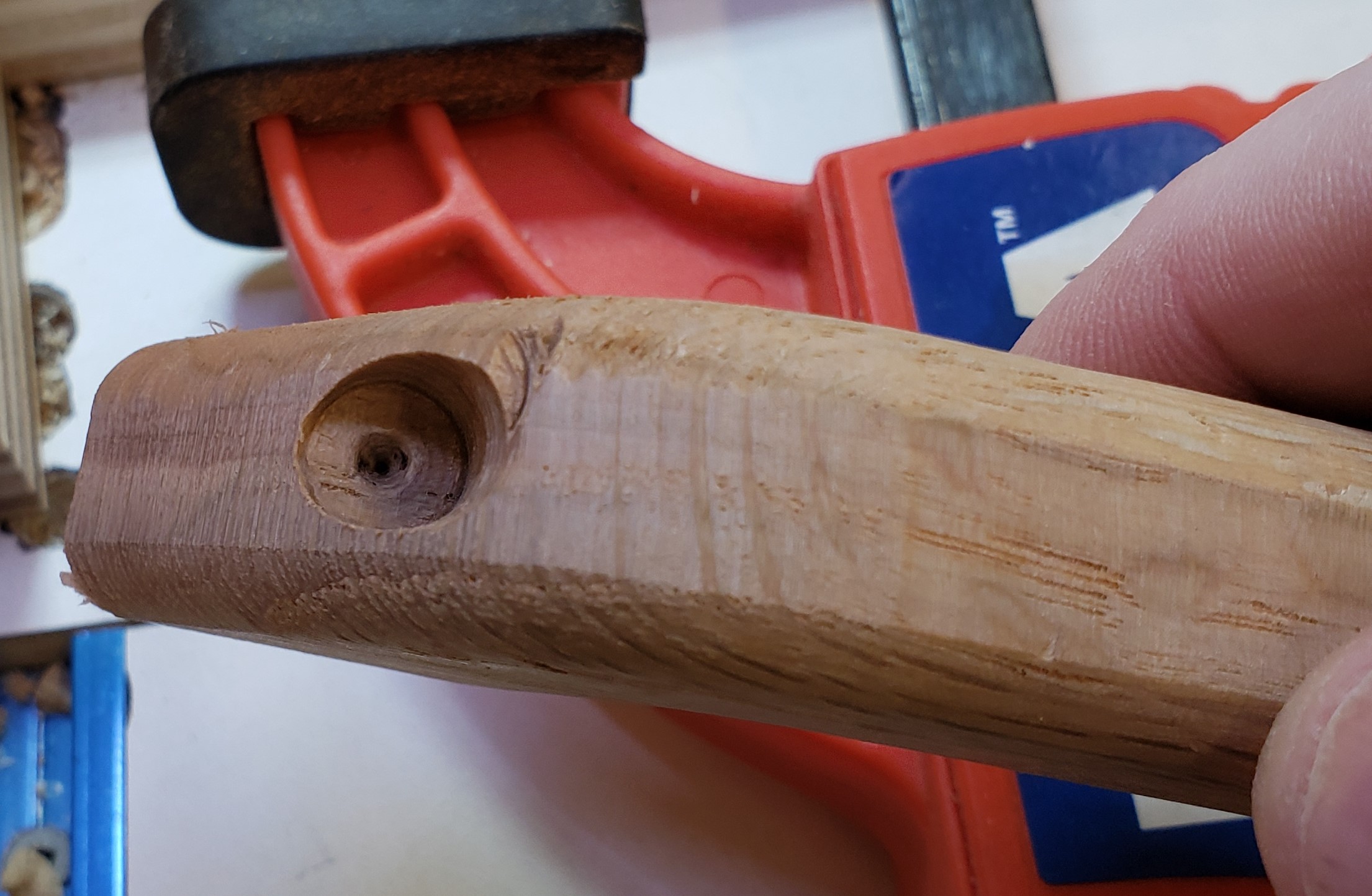
Next the handle blanks got sanded, a round over, and more sanding. I figured I would make their look a little more industrial, and set to counter bore the front for a screw. Lots of stop blocking and clamping was needed for that. This would be stronger than screwing through the back, and easier to install. I like the aesthetics of it too.

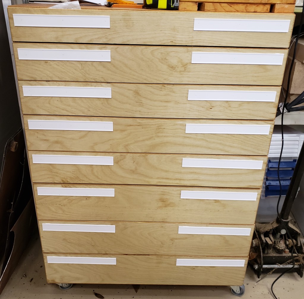
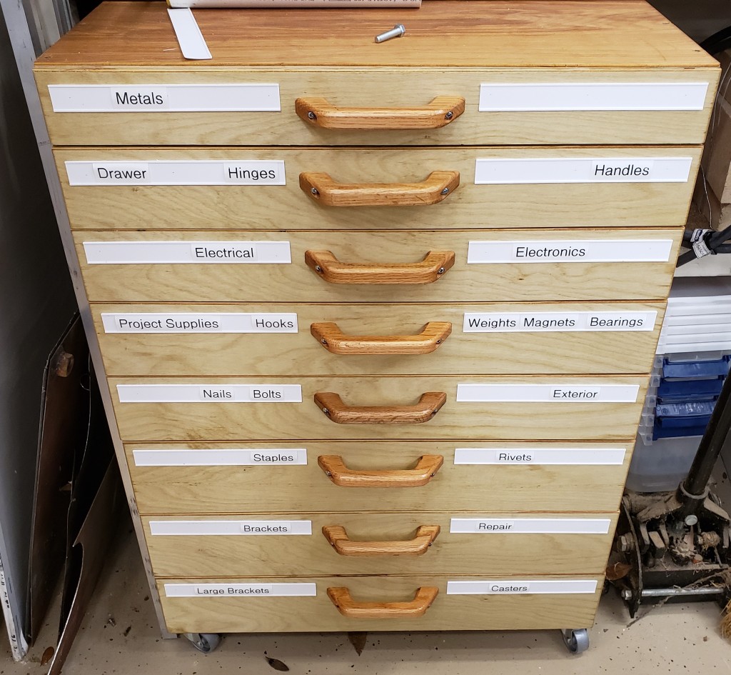
Things were coming together. I needed some labeling, so I printed slots that would accept 1″ label tape without the back removed. It meant I could rearrange tags quickly without peeling anything. A little calking on the back held the holders down. I used a few pin nails to tack them in place while the calking dried. No heads on the pins means they don’t interfere with the labels sliding in from the sides.

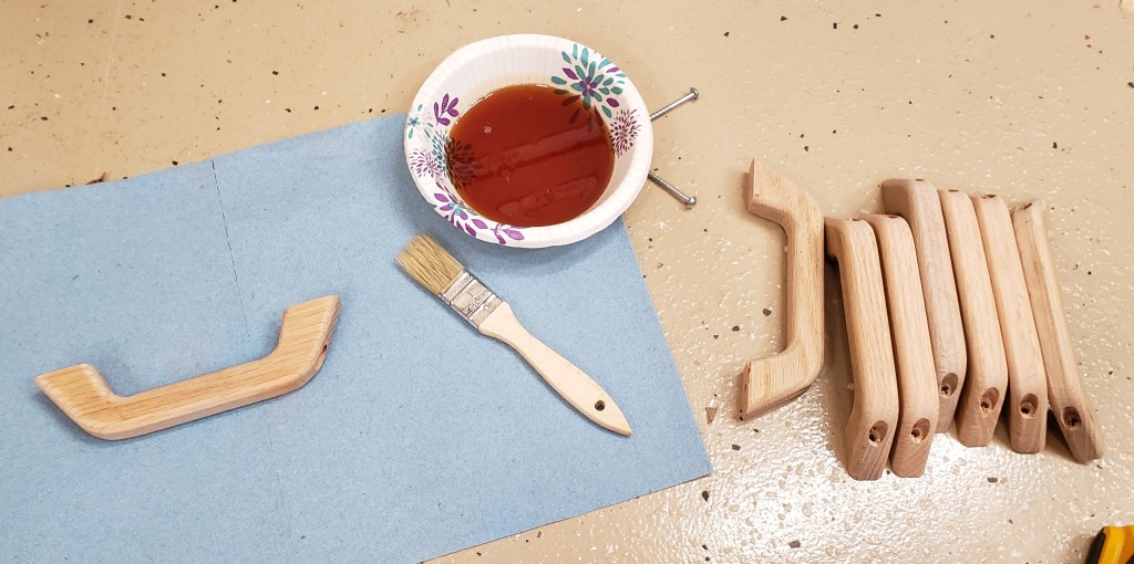
I painted on a little linseed oil on the handles and installed each one down the center. They are comfortable, easy to use, look gorgeous, and finish off a wonderful cabinet. I should make my own handles more often. I feel like my experience and planning payed off. Other than some issues with the handles this job went off without a hitch. I have done a lot of other stuff like it before though, so I shouldn’t be making as many mistakes at this point.

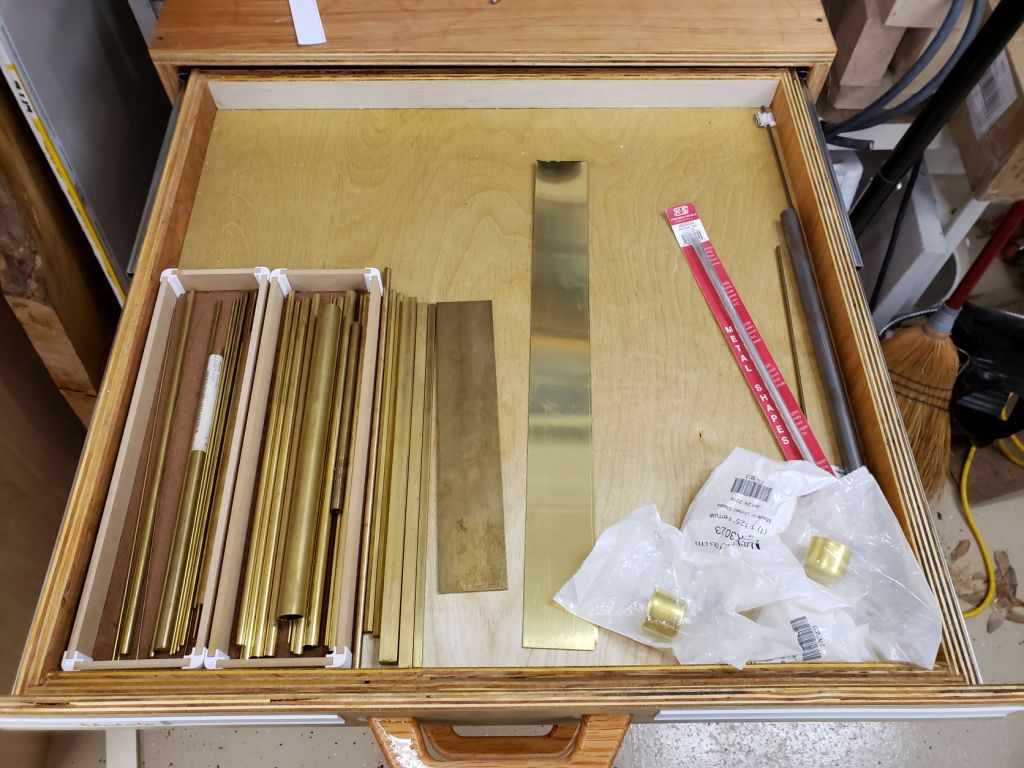
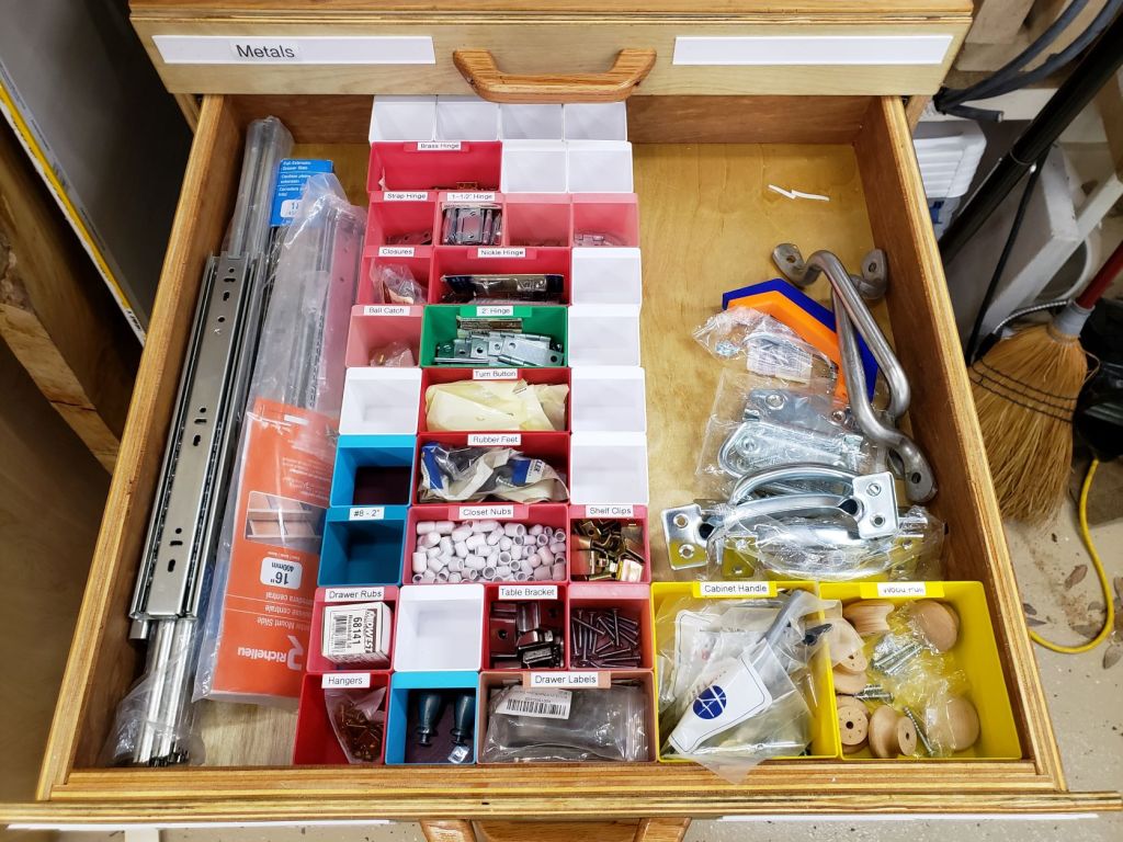
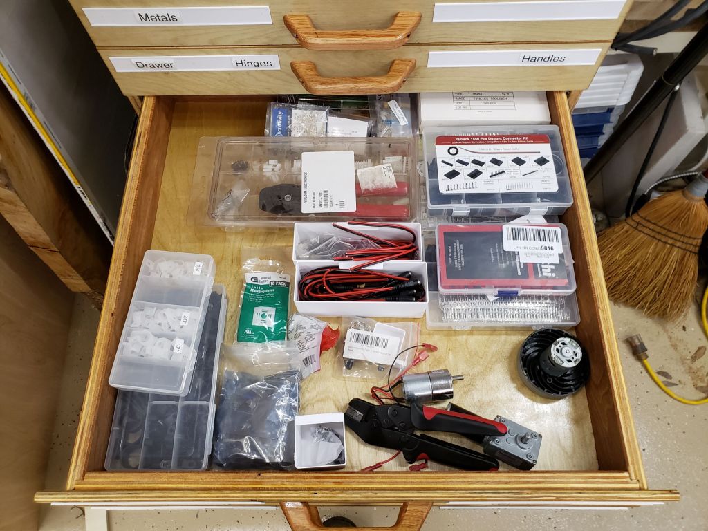
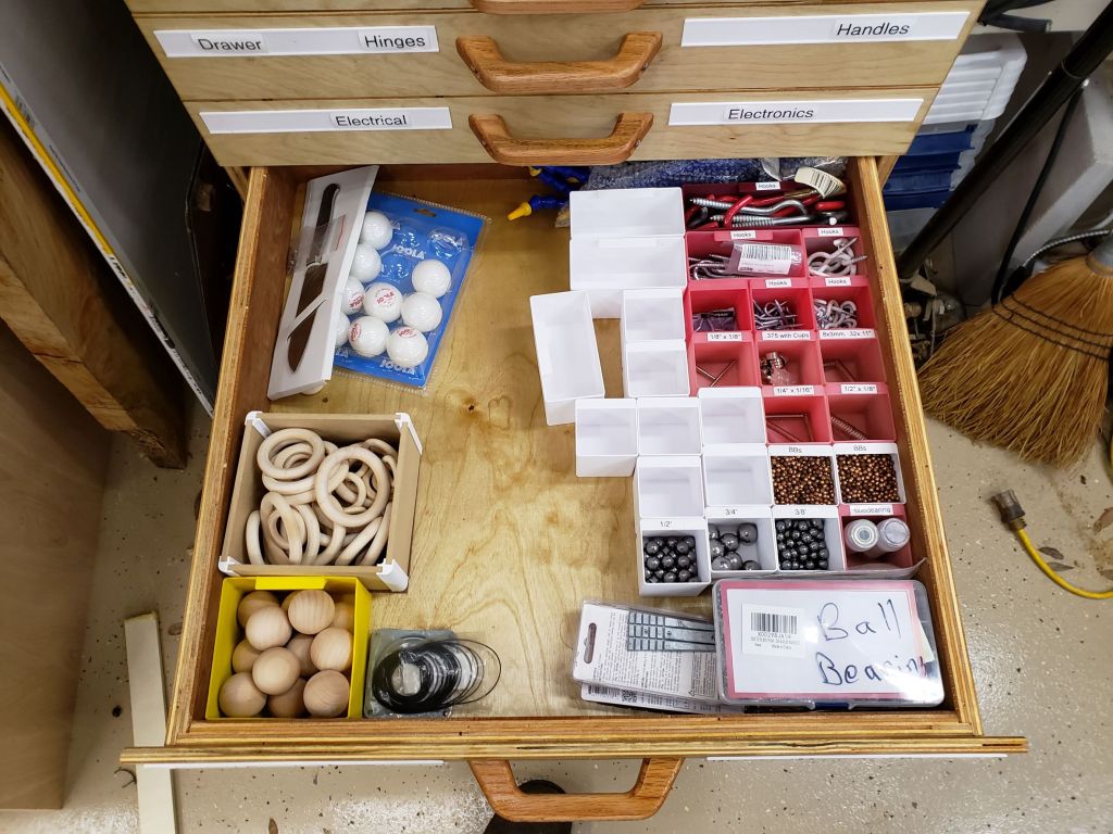
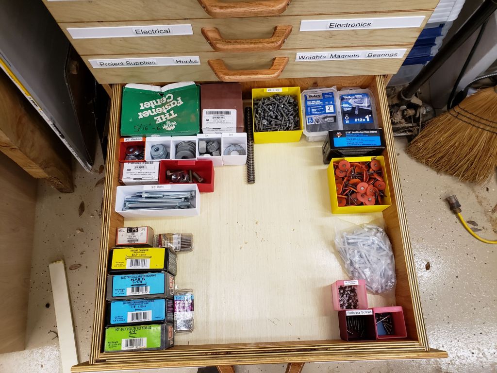
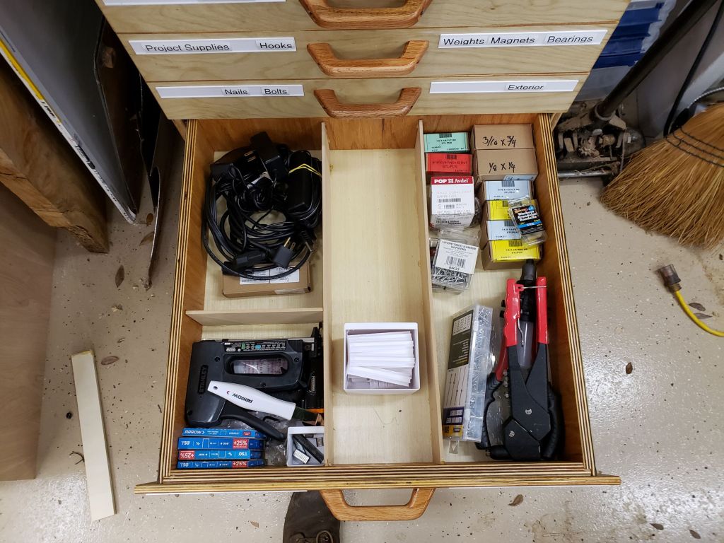
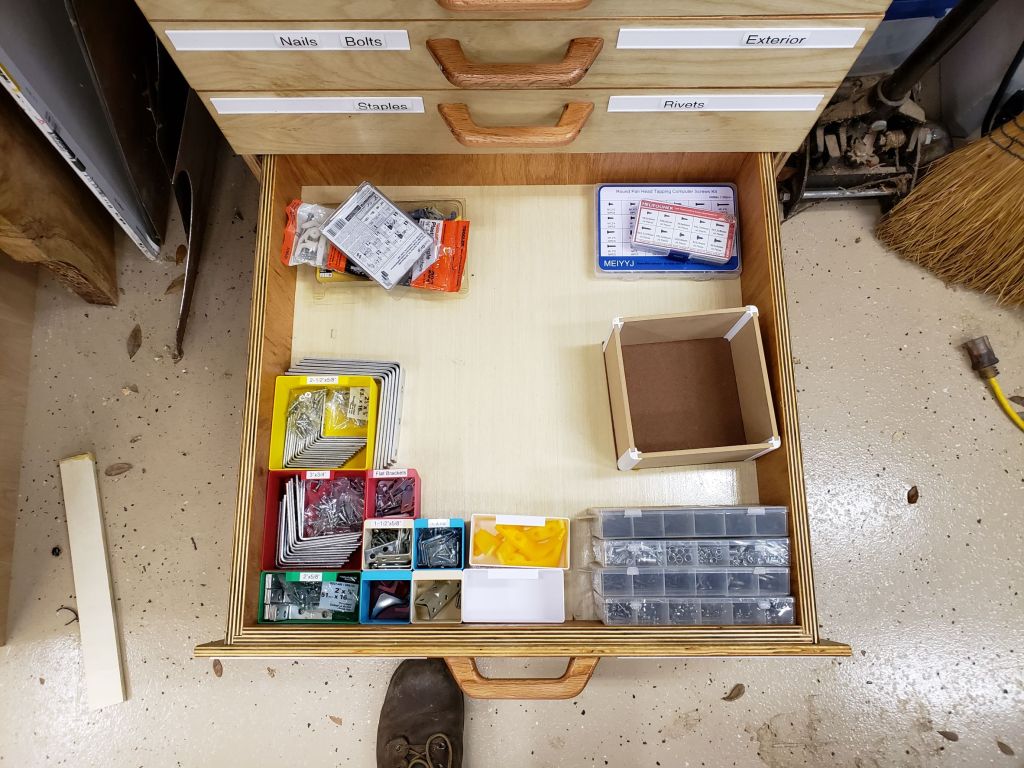
I spent days pulling things out of bins and drawers, organizing, cleaning up and throwing away junk. This isn’t the final configuration, but it is close. The shelves are a lot cleaner and I still have a lot of room left in this guy. It isn’t hoarding if you use labels!

Spray Paint Crate

I picked up a few extra cans of spray paint for different things I have in the works. Those added to my modest collection of paints meant I was way over capacity in my limited storage arrangement. I tossed out the old setup (which I forgot to take pictures of), and built myself a set of spray paint crates. This was a nice small project, but probably the biggest woodworking thing I have done since Ira came along. It is good to make sawdust again.

Every good shop project starts with some plywood. I had a lot of 1/2″ lying around from the toy and baby furniture days. The front, back and bottom are 1/2″ ply glued and nailed together with 1/4″ glued and nailed to the sides. It made for a pretty stout box without being too bulky or heavy. With 18 fullish cans, this thing was heavy enough.

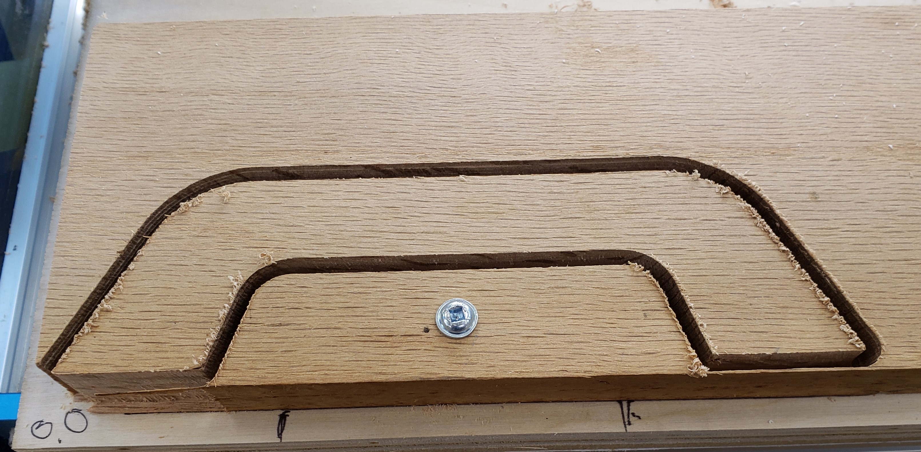
For the front and back handles, I could have just drilled out the sides and used a jigsaw, but I wanted something repeatable and re-usable. I 3D printed a jig with a sized cutout for my hand and with a reasonable offset. There is a notch in the center so I can line it up with a mark. Not sure how often I will use this jig, but it was cheap to print, worked like a charm, and should last a long time.

With the handle cut out I rounded the corners with my corner radius template and then used my trim router to round everything over. Some quick sanding later and the handle area was smooth and comfortable.

The assembly was as mentioned before. Glue and brad nails. I eventually let that dry and put a coat of boiled linseed oil on these to make sure they stay together for a long time. They are just the right size for fitting in the bottom shelf of my paints cabinet. It need more cleanup and rearranging to get the second one in there. That calls for more shop organization!

Folding Helping Tower

A helping tower is like a step stool you use in the kitchen with a child. It gets them up to a height to be able to help out with basic cooking tasks. Unlike a basic step stool, this has sides and a back so they can be kept in place, and not easily fall off. There are a million different examples online, but most all of them are bulky (by necessity) and end up being a bit of an albatross in the kitchen. I wanted a folding one that could be packed away easily. It took a lot of prototyping, but I did it.

I normally jump into projects, but this one was a very slow methodical trial and error build over nearly 2 months. A broken AC and baby tasks stretched that out a bit. The front frame of the device consists of two permanent uprights with an upper and lower stretcher. To those uprights, a set of folding sides are attached. The right upright is thinner so that the two fold over each other in an overlapping pattern.

The middle stretcher will hold the step and let it swing into place. I needed a strong stop that would support the step and draw the sides into the step. I used a dovetail bit on the bottom of the step to make a slightly angled groove. The stops had the same angle in reverse. Now, the more weight put on the step, the tighter it will draw the sides in.

The seat can fold up and the sides fold in. Everything is compact and easy to deploy. The stops are only 1/2″ thick and don’t interfere with the fold up.

It needed some kind of back to keep people from falling off backwards. A simple swing arm accomplished this task. It was narrow enough so as not to interfere with the unit’s ability to pack up. This had all the rough mechanics I wanted, but was narrower and not as deep as I felt it should be. Also I wanted the step portion to be adjustable as the child grows. On to the next prototypes.


I am going to use dowel nuts and binding screws to make something that was strong, but could be removed and reassembled. It would take a number of holes drilled in the right places to make that work. I planned the sizes of the parts and printed out drill guides that would hold brass tubes to act as drill bushings. The brass won’t last forever, but is easy to cut and insert, and helps keep the hand drilling accurate.

First up I clamped the jig in place and used a transfer punch to mark the centers of where the barrel nuts will go. This makes drilling on the drill press easy.

Next to accommodate the bolts, I need to drill a long hole end-on to meetup with the cross holes. This can’t vary much and the parts are too long to use the drill press, thus the drill jig idea.

With both sets of holes accurately drilled, the nuts and bolts will meet up in the correct spots.


With the folding and adjusting mechanics worked out I could move on to the real thing. I selected 1×3 pine for the uprights and spreaders. The step spreader got its holes drilled with the above jigs, and the other two spreaders received a set of fair curves thanks to my new drawing bows.

Part of the assembly folding out and being stable is having the sides only fold out 90 degrees. They must positively stop when they reach the right angle. I do this by firmly clamping the sides and uprights together and routing a small pocket for the hinges. This 3d print has a center-line mark on it and is perfectly spaced to make a tight mortise for the hinges. The result is a flush hinge and sides that do not swing out past where you need them.

I assembled the step and determined how high it could go when folded up. Too high and the step hits the top spreader. Marking those places I could make a row of holes that would allow the step assembly to adjust as needed. The sides and uprights got a set of holes placed every 2 inches.

To lighten the structure and add something fun, I printed a series of shape templates. Double sticky tape holds them down, and a plunge router cuts them out quickly. I made 8 unique shapes and it really adds a lot.

I put the center spreader in at the top most position and marked where the stops should be. Each one has two t-nuts hammered in place. Bolts go in from the outside to hold those securely. Now to adjust the height you have 8 bolts to remove. 4 from the stops, and 4 from the folding step. The final unit is light, compact when folded, looks decent (even though most of it is plywood), and should have enough room for any kid small enough to need it. The swinging back stop is made with another set of dowel nuts and binding screws. Everything got a coat of shellac as basic protection.

As a final bonus, I was able to cut the shapes out carefully enough that they all survived in tact. I rounded the edges and shellacked them as well.

I want to be able to re-create this again in the future. Here is a rough parts list with sizes. Dowel nuts and binding screws are both 1/4-20s.

QtyDescription
6Dowel Nut
4Binding Screw, 5/8”
6Binding Screw 1-3/16”
4T Nut
8Pan head screw, 1-1/2”


1Back Bar: 18-1/4 x 1-1/2”
3Spreaders: 16 x 2-1/2”
1Upright Left: 38 x 2-1/2”
1Upright Right: 38 x 1-3/4”
1Side Left: 36 x 10”
1Side Right: 36 x 10-3/4”
1Step: 16 x 11-1/2”

Wee Walker Fleet

My first wee walker was pretty popular with kids of the co-worker I gave it two and didn’t need any revisions after the second version. I wanted one for us, and I had two co-workers that were having kids soon. That calls for a batch run!

The MDF templates I made earlier came in handy. I could use them to do rough dimensioning of the plywood, and it let me efficiently nest parts together in some cases. I didn’t use them on the router table, but opted to free hand cut everything on the bandsaw. I was going to have to bandsaw the basic shape anyways, so all it took was a little extra care to cut up to the line. Power sanders took care of the rest. These aren’t very complex shapes.

Cutting wheels this big is kind of a pain. A 4 inch hole saw requires a lot of torque, and getting the sawdust out cleanly on 3/4″ plywood means constantly pulling the bit out and cleaning it. I might 3D print the wheels next time. 30% infill ought to be kid proof right?

I changed up the paint scheme a little from last time, adding black to the wheels and a stripe of black on the sides. I left the handles bare wood. This looks pretty nice on them, and isn’t too much work.

Everything is coming together with roundovers and pilot holes being drilled.

This round of building went well, with only a few minor errors. I made the holding area a lot deeper front to back, and that might be a mistake. It had the arms really close to the wheels, and might lead to kids kicking the back plate when walking. I don’t think it will be a major issue, but will want to have a shorter storage area in the next version. I’ll have to start calling myself kilted santa’s workshop.

Wee Walker Wagon V1 and 2

Getting back to baby furniture, I have seen different kinds of little pusher wagons that kids learning to walk can use to help them build muscles and coordination. A co-worker mentioned that his daughter had a plastic store bought walker that she was learning to walk with, but that it was so light that it would shoot away from her. I had him measure her height to the shoulder to act as a rough starting point

I will probably build one for us and a few for friends having kids. That means making use of templates to repeat the work once I figure out what I want it to be like. I broke out the compass and thin bandsaw blade and got curvy.

I added holes to the templates and used a transfer punch to copy those holes over to each part. That way the wheels will connect in the same spot, and the handles will go on evenly. To add a little color and flare I painted green accents to the handle and wheels and a racing stripe for +2 speed. When the paint was all dry I coated everything with polyurethane.

I was worried the walker would go skidding across the floor if placed on anything other than carpet. I printed thin TPU bands to act as tries and glued them to the wooden wheels. The TPU isn’t as grippy as a rubber tire, but I was able to produce it in house and it will grip better than the bare wood.

I spent some time fiddling with the arms, and probably built them a little too short. I will give this to the co-worker and have him test it out on his daughter.

The finished product looks nice. It is heavy enough that a child just learning to climb up will not have it shoot away, but light enough they can still push it. Lock nuts set the tension at the wheels, so there can be more or less resistance as needed.


I gave this one to the co-worker that was complaining about the plastic one his daughter was using. The only catch was that he had to report back how it worked, and let me tweak it if need be. A few weeks later the reports were in. The bigger kids liked to play with it too! They treated it like a bumper car and crashed it into a lot of things. Also they wrenched on the handle hard enough that the arms were flexing where they screwed into the body. Lastly, it was a little on the wide side.

No problem, this is why I gave it to him! I didn’t like how the old arms turned out, so I went ahead and remade the template. Instead of freehanding some curves I got more systematic. I drew two circles that were the size I wanted each end of the arm to be, and drew them further apart than the original arm so I could move the base down lower on the cart. Then, to connect them, I set my drawing bow to a nice curve and connected the tangents of the two circles. The results look a lot better than my first arm template.

I assembled everything with pocket hole screws from underneath, and a few visible screws on the side. That let me take everything apart for alterations. I trimmed the center width down from 16 inches to 12. That should lighten the look and load of the thing and make it more maneuverable.

The bumper car comment had me wondering. I had left the bolt heads stick out beyond the wheel. If they caught a piece of furniture or baseboard, the bolt would probably fair better than the target. Also, there wasn’t much cushion to the tires. I mostly added them for grip, not as a bash protector. I counter-bored all the wheels, to recess the bolt heads, and upgraded to 5/16″ bolts as that was what I had available. The old tires were cut off and replaced with thicker ones that wrap around the outside face of the wheel. Now they shouldn’t be so offensive to fine features in one’s house.

With those upgrades complete I reassembled everything and gave it back to my co-worker. If there aren’t any more changes needed I can go into production and make a few for myself and other co-workers that are having kids.

Table Saw Outfeed Extension

I already had an outfeed extension for my table saw. I only built it two years ago. Why make a new one? Well I love it and use it all the time, but often wish it was bigger. Wide sheet goods don’t get enough support on the side, and longer things still fall off the back of it. I have more space in my new house, and I saw a great idea from Wood Work Web. Colin over at that site used these clever folding brackets to hold the extension and in a followup added a really easy release bar. First, let’s say goodbye to the old extension.

How did I manage to get nice laminate faced plywood in these times? As it turns out if you order enough sheets of plywood from the cabinet store, they will deliver it all for a pretty reasonable fee. I got enough supplies to last me for months, supported a local business, and did it in a socially distanced manor!

The folding brackets are a cheap amazon versions of what was used in the video. They feel sturdy enough, but aren’t actually square. A deeper read of the comments would have highlighted that fact. They slope the table away from the saw. That is ok by me, but in a lot of other applications, that could be a deal breaker. After removing the old top, I was able to re-use the bolted on pine board that served as the anchor point for my previous extension. I spaced the extension far enough away to clear my fence and its hardware. There is a bolt head (circled in red) that sits well below the height of the table. I have to avoid it or risk limiting the fence’s movement. Once installed the extension folds very compactly.


Rounded Corners

I really wanted to cut some corners on this build. I know I will be lazy and leave the extension up most of the time, and I work a lot around the table saw at my router and back into the saw and extension often. Rounding these edges would make them less painful. I started with a 2.5″ radius template and used it to mark and jig saw the corner off. Next I stuck it down with double sticky tape and used a template tracing bit to smooth out the remainder.

Once both corners were done I applied a white edge banding to all the edges. This should help protect the laminate top from getting chipped or damaged. I trimmed all the excess with a sharp knife.

Miter Slots

My last extension didn’t have any miter slots. If I used any kind of sled or miter gauge they would bonk against the table. I took the time to install them in this top. I clamped plywood to the top just outside of where the miter bar would pass. I then used a short tracing bit route down enough to allow clearance for the bar. I then picked up the plywood, lined it up with the other side of the bar and routed again. It wasn’t as exact as a purpose built slot template, but was quick and worked well. With the two slots routed, I soaked the edges in thin CA glue to help reinforce them and prevent the top from chipping off.

Things were starting to look really nice and functional. I did notice that my last top had a slight warp to it. I may have stored too many things on it. To prevent warpage in this top, I took it off and screwed on a set of supports underneath. These should help keep it flat.

Release Bar

This was kind of above and beyond, but why not go all out? I wanted to add a release bar like Colin did. Between the supports I added, and the way it was anchored to the saw, there wasn’t room to do what he did. Instead I 3D printed a little funky zigzag bracket. It is threaded to accept a #10 screw. I drilled a hole in the bracket release tab so the screw would go into that hole and prevent the bracket from sliding off.

That printed part gave me a long arm to attach a wide piece of plywood. This would be the thing I press up against to release and lower the extension. I clamped it in place to make sure it was all working correctly, then screwed the release bar down.

The finished product is great! It holds a lot of weight, gives me plenty of support for wide and long cuts coming off the saw, and folds up really flat. I figured the ease and speed of pack and deploy had to be shown, so I made a short gif.

Router Table

While building my baby bookcase I noticed the table top on my router was not flat. The joinery was poor enough I had to go to the table saw instead. 10+ years of Florida humidity and a heavy router finally did it in. The red arrow is pointing to all the light coming out from under the straight level.

I use my router table a lot, so I wanted something nice to replace it. A full professional router table setup can cost 1,000 bucks with all the bells and whistles. I want something of decent quality, but not for that much money. I did a ton of research and finally broke down to buying a really high quality lift, and building the rest. Say goodbye to my old friend! By the way, I took the mounting plate out and tried it on my tablesaw top. It had a very distinct rock, so it wasn’t flat either.

The Top

These days my building and blogging are badly out of sync. Some short projects get posted in a week or two, and bigger ones linger for months before getting posted. This one started right about the time we were all supposed to limit our trips out to essentials only. The hardware stores are open, but I can’t call this router table essential. A broken toilet or water heater, this is not.

I normally would have gone to pickup laminate faced plywood, but instead I looked around and decided to use this big piece of butcher block counter top. Some friends were having their kitchen redone and saved it for me.

I got to cutting off a nice hunk and my saw went a little nuts. It turns out the way they clamp everything together is with screws! Lots and lots of screws. If you look at the side, they even cut through some to make the counter top the right size, and just filled the void with putty. They must make these things in massive sheets, then cut down what they need.

I took my number 5 to it and planed off all the old finish that was feeling a little gummy. It looks a lot nicer now. This is really soft pine and not as flat or as stable as I was hoping. There was some twist I couldn’t quite get out.

With the top mostly flat, I built up a set of guides to install my router lift. This part didn’t go quite as planned either. I tried to attach each piece together with pocket hole screws, but going into the plywood sideways with a screw caused it to de-laminate and bulge. I muddled through with double sticky tape and got to routing with a template bit.

Once I had a recess routed that was the thickness of the router lift top, I went through and cut out the inside area. Those pesky screws came to bite me again, my jigsaw was not happy. When it was all cutout I marked the location of the leveling set screws and soaked the area with thin CA glue to stabilize the wood. I was worried the set screws would slowly sink into this soft pine otherwise.

The top’s twist was a little evident in the fit of the router top, and the template bit’s radius was off. It turns out the lift has a corner radius of 3/4″ of an inch, and my bit is 3/4″ in diameter which yields a 3/8″ radius. I think we are going to call this a practice table top. I will eventually get a new material and make a better one. I put down a few coats of polyurethane to seal it up and give me a solid surface to wax.

Base

With the top basically finished I was able to move on to the base. Using the plywood I had available I made a 3 chambered base. The left was going to be for open storage, the center would house the router and collect most of the dust, and the right would have a set of drawers for bit storage.

I set the top down and the twist is even more evident. The bottom is really uneven, so I guess they only ever planed the top to flat-ish.

I thinned down some maple scraps and cut them up to make runners. I used a piece of hardboard as a template for the drawer side height, and it also served as a square and guide for installing the runners. I nailed and glued those in place, then hit everything with boiled linseed oil to finish.

Fence

I had some ideas about how I wanted to make a fence, but wasn’t quite sure which way to go. I was also running low on some materials, so to conserve, I just re-purposed the fence from my old router table. I added wings to make it reach out further. To hold it in place I made it go past the edges of the table, then used a little clamp paw to squeeze it down to the edge of the table.

To attach the wings I just screwed them down from underneath

It worked reasonably well, except that any time I pushed on the fence in the center, it seemed to bow outward. The system wasn’t rigid enough. I added a support across the back to help stiffen it up. That reduced the bow. Next time I will sink some tracks into the table top to facilitate more centralized clamping.

Drawers

Things were starting to come together. With the top in place and a working fence available I was able to employ it in making drawers. Nothing fancy, just some plywood sides with half lap joints and rabbeted bottoms. I added drawer fronts with rounded edges and finished everything with boiled linseed oil.

The top drawer holds my trim router and all 1/4″ shank bits. Only got this thing a month or two ago, but have found it to be an incredibly useful tool.

Next are all of my 1/2″ shank bits. They fit with plenty of space to spare. I 3D printed the holders for these because I didn’t have the right sized drill bits. A 1/2″ bit will leave a really snug fit. My next size up was a 5/8″ forstner bit. Too loose! Everything is kind of grouped and there is a lot of room left for new bits. The last drawer is empty believe it or not. Plenty of room to grow!

Finishing Touches

With the drawers set I was able to work on a few finishing touches. I moved the power switch over from the old table to the new one. This works great and will stay. There is a hole in the back for the router’s power cord to come through. I covered it with a custom 3D print cover. I put a cover over the front router cavity with magnets. It comes right off if I need to service something, but otherwise has gaps to pull air and dust through when in operation. On that cover I have two printed holders with magnets for the collet release and hex tool that runs the lift. Lastly I added a shelf to the left cavity. It holds common use accessories and a stack of different brass setup bars I cut from 12″ lengths of key stock.

I have been using this table for a few weeks and it has been working really well. The router lift was pricey, but is a dream to work with. It adjusts easily and locks down securely. The top is fine for now. The pine has already gotten dented and my install job has left some gaps. The fence clamps work well, but it flexes too much. I will take all these lessons learned and do a series of upgrades soon. For now, it is back to work on other projects.

Baby Bookcase

Our household bookcase is already pretty full with regular adult stuff. A new kid will require more book space. I always like those ones that would face all the covers forward. They of course sell for a lot, but with a bit of plywood I can make my own. Final product first, so you can see where we are going.

Our small collection of baby books ready to go! The only thing I would do different next time would be to make each pocket shallower. Lots of kids books are only 4 or 5 inches high, so they get half obscured.


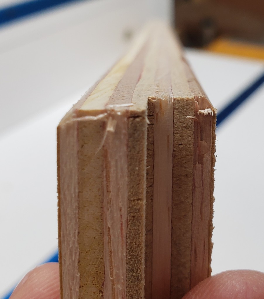
I wanted to make a locking rabbet joint to hold the bottoms of each shelf on to the back. I used a slot bit on my router table and had numerous issues. This plywood tears really badly without any kind of support around the small diameter slot cutter. Those Jagged edges are really nasty and will be a pain to deal with. Good thing I cut a spare shelf to experiment with.

The other problem I was having was that my joint didn’t seat up very tightly across the wide shelf. I re-did it twice and still had odd gaps. I started looking at my router table and found the source. That is a straight level on the table, and the red arrow is pointing to a very large gap where the flashlight beam is shining through.

The router table is made of MDF, and the center plate that attaches to the router is plastic. Both had sagged after 10 years of weight and humidity. No wonder my cut wasn’t straight, my table isn’t flat! I will have to fix that later. I setup the tablesaw with a 1/4″ dado blade and cut all the joints. I hate having my table saw tied up for doing joinery, but it did make the cuts a lot cleaner than the router did.

With that solved I assembled all 5 shelves. Each one has pocket holes in the base so it can screw into the shelf in front of it, and more pocket holes along the sides to screw into the uprights. I finished all the shelves and cut out the two outside uprights that everything else would screw to. Other than the locking rabbet to attach the back and bottoms of each shelf everything else is pocket holes. Not glamorous, but effective.

For finishing I decided to try my hand at spraying shellac. I broke out shellac for the first time in a while on the stacking block project, but picked up a compact HVLP spray gun to try this out with. I reduced the shellac down to a 1lb cut and sprayed away. I didn’t have the gun setup right the first round and wasted a lot of finish. The second time I got it tuned in and was able to apply a few coats in a very short amount of time.

Before
After Shellac

The shellac is dry to the touch in a few minutes, and with a little buffing, the next coat is ready to go on. Once the solvent evaporates it is set. Each successive layer will re-desolve the previous a little, so it always sticks. Not the most durable finish, but kid friendly and easy to repair.