
I take things too far sometimes. This is one of those cases. At work I frequently align things to microns and worry about nanometers. That followed me home a little. My new CNC mill is running, but has some odd issues. The bed isn’t very flat, and that means fine things like engraving can end up with issues.
This is an early project I did. Storage for the mill. I engraved all the letters in one go, milled the pockets, did some chamfering and cut it all out. The “Up Cut” letters are barely there, while the “Ball End” is very bold. That isn’t by design. The bed is higher on the right and makes that part cut deeper.

I bought a dial indicator just for this, and went to work measuring the issue. Holy cats was it bad. I didn’t have enough range to know for certain what I am dealing with. At least 0.04″ across the middle, but likely much more than that. Enough to sink or float an engraving tip right off the part.

I thought my spoil board was part of the issue, so I pulled it off and went about measuring the aluminum underneath. Actually there was a whole step in here where I printed shims and shimmed up the bearing blocks trying to flatten it out. I’ll leave that stuff out, the aluminum bed is nowhere near flat.

Ok, no problem. The aluminum bed is wavy, I’ll just fix that. I got a bed flattening bit and set it up to go really slowly over the bed and nibble away until I pulled out the high spots.

Not great. This little router isn’t stiff and can’t handle aluminum. It grabbed, hopped around like a mad hornet, and the spindle slipped up. After a few fouled attempts I gave up and tried a new tact. I have seen other hobby cnc routers use an aluminum bed with MDF inserts. I put down double sticky tape on all the extrusion parts, then stuck down 1/4″ MDF.
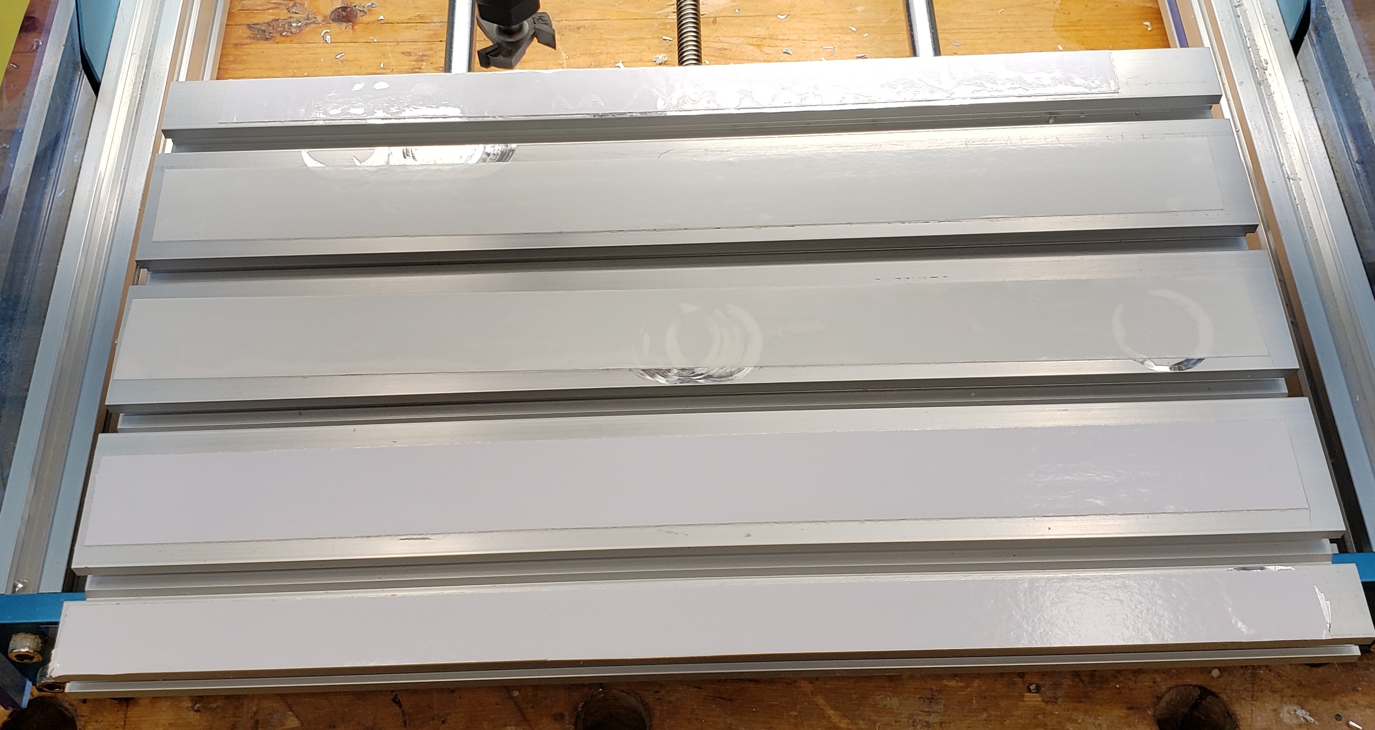
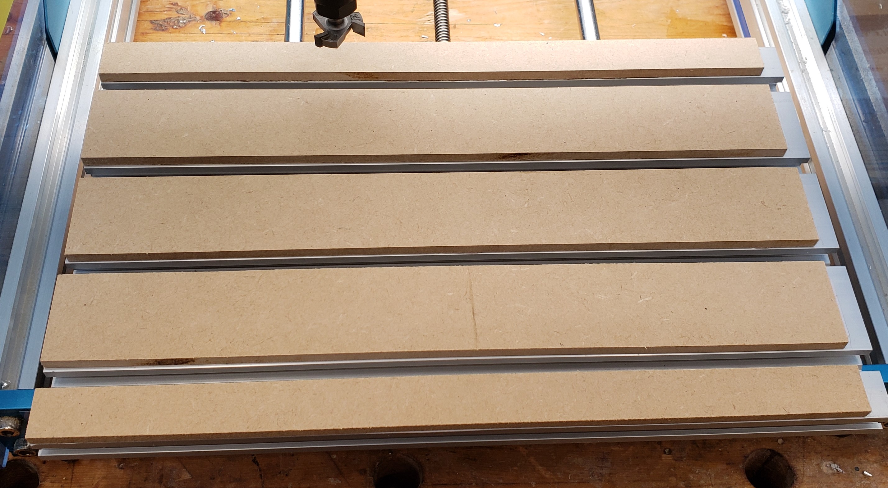
I rubbed down some thick sharpie to help me visualize where the bit touched, and where I still had a low spot. I did a 0.02″ first pass and it showed a low spot still in the lower right. Another round cleaned it all up. I had another issue though, there were ridges every time the router bit went past.


I put down the waste board again and installed my indicator to make some measurements. Much flatter now, but those ridges kept bothering me. Every pass left a ridge in the previous pass’ overlap. I spun the indicator around. It was touching in the front, but way up in the air when spun around to the back. That means my Z axis isn’t perpendicular to the bed. It is tilted forward.


To fix this issue I need to loosen all the bolts that hold the X and Z stage down, tilt it towards square, then re-tighten. It took a few tries, but I got it.


I redid the bed flattening and this time no more ridges. I got it squareish! A little bit of the mdf lifted on the left where my finger is, but otherwise my dial indicator read pretty flat across the board. I installed the wasteboard again and got a hump in the center. I think bolting it only on the corners is causing a hump in the middle.
To remedy this I need 6 hold down screws. That is tough though. Getting that center t-nut in and aligned can be tricky. To capture them, I 3D printed small plastic t-nuts to accept M6 set screws. Those will act as holders to capture the main bed t-nuts. I measured the locations, and can mill all the needed countersinks from the home position.


Finally, I wrote a program to cut the counter bores for my new bed, pulled out a fresh piece of 1/2″ plywood, and milled away. Once installed I broke out the indicator again and measured around 0.005″ of flatness error. Not bad considering there is plywood involved. Finally, I can rest. Actually, it is on to the next milling project!


Your thoroughness and attention to detail (and the solutions that you ultimately come up with) never cease to amaze me 🙂 I look forward to wonders that you will make with this!
LikeLike
Awww, thanks buddy!
LikeLike